
Control Circuit for a Window Lifter Drive

Active Publication Date: 2011-11-24
BROSE FAHRZEUGTEILE GMBH & CO KG HALLSTADT (DE)
View PDF1 Cites 18 Cited by
  • Summary
  • Abstract
  • Description
  • Claims
  • Application Information

AI Technical Summary

Benefits of technology

[0014]The change in the lighting current is therefore known to be an indication of a case of inundation and can therefore be used as a particularly simple and reliable means of detecting such a case of inundation. In turn, a switching criterion or control criterion which ensures reliable actuation of the window lifter drive in the opening direction of the vehicle window can be generated on the basis of the detected change in the lighting current.
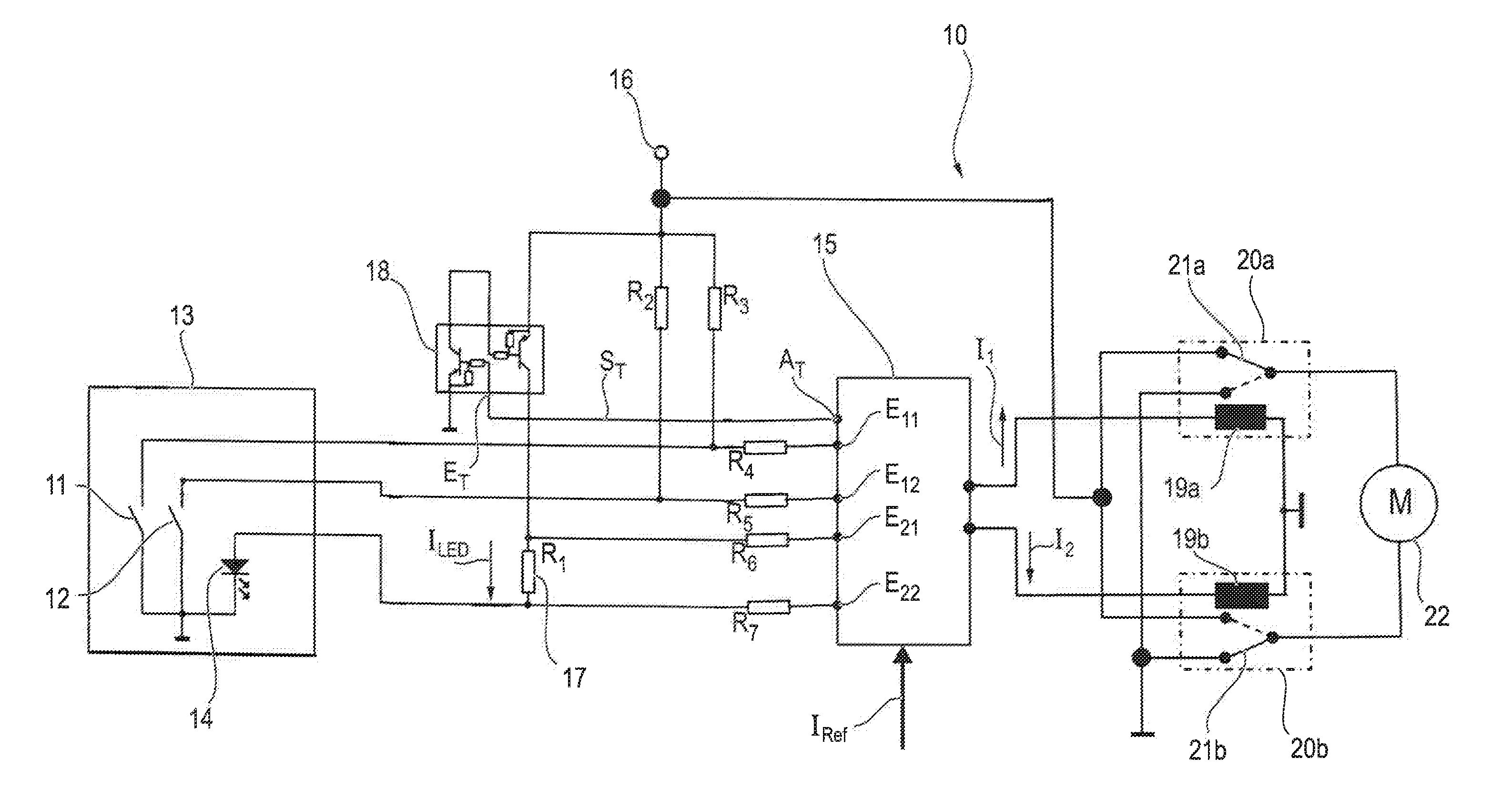
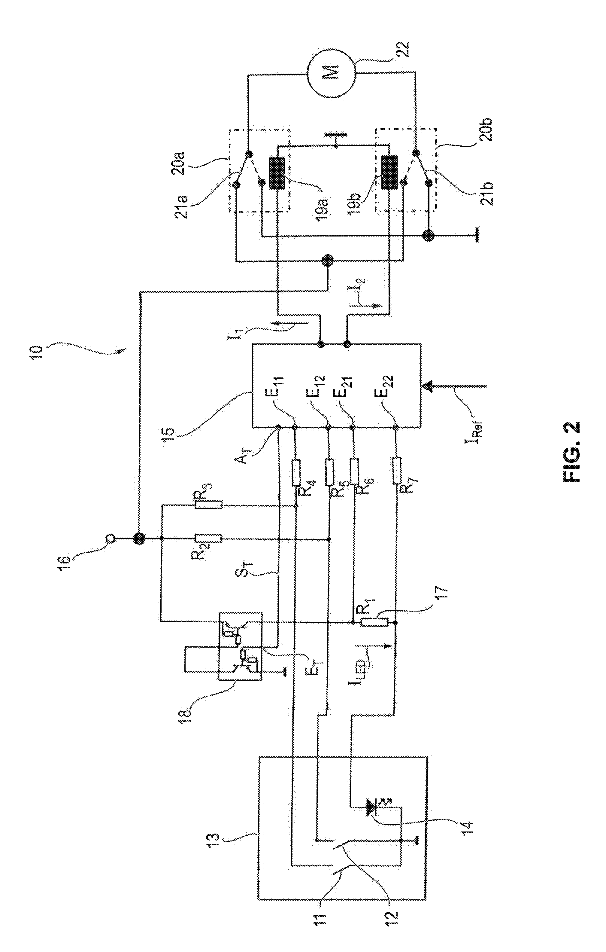
[0019]The advantages which are achieved with certain embodiments of the invention include, in particular, in the fact that inundation of the vehicle is detected with simple means by detecting a change in the lighting current which flows through a lighting element for the operator control switches (pushbutton keys) of a window lifter of a motor vehicle. A voltage which can expediently be tapped at a shunt as a preferred current sensor, which is connected in series with the lighting element and between two signal inputs of the control device, which voltage is proportional to the lighting current and can be used, as it were, as an inundation signal, can be detected particularly easily and can be reliably evaluated by means of the control device with respect to correct actuation of the window lifter.
[0020]A particularly reliable control circuit of the window lifter with an unambiguous control signal for opening the vehicle window is therefore made available which considerably increases the safety of the vehicle occupants, in particular in the event of an inundation accident of the motor vehicle.

Problems solved by technology

Undefined states or levels at the signal inputs of the control device are problematic here, with the result that a correct interpretation is not ensured.
Undefined states occur, in particular, if moisture and, in particular, water penetrates the switch system which comprises the switching contacts of the switches or pushbutton keys for lifting and lowering the vehicle window.
In particular when the vehicle is immersed in body of water, the vehicle and therefore the control circuit are inundated.
Undefined level states which are caused as a result of this and which result from short-circuits can lead to the vehicle window no longer being able to be opened in order to permit the vehicle occupants to use the window to exit from the vehicle which has been involved in an accident.
Such a detector signal causes the energy supply to the relay which is responsible for the movement of the window pane in the closing direction to be interrupted, with the result that the vehicle window can then only be driven into the open position.
The control device, which is connected to the driver circuit via a corresponding signal output, therefore causes the driver circuit to be switched on and off with the result that the lighting element is, or is not, supplied with the lighting current.

Method used


Image

  • Control Circuit for a Window Lifter Drive
  • Control Circuit for a Window Lifter Drive
  • Control Circuit for a Window Lifter Drive

Examples


Embodiment Construction

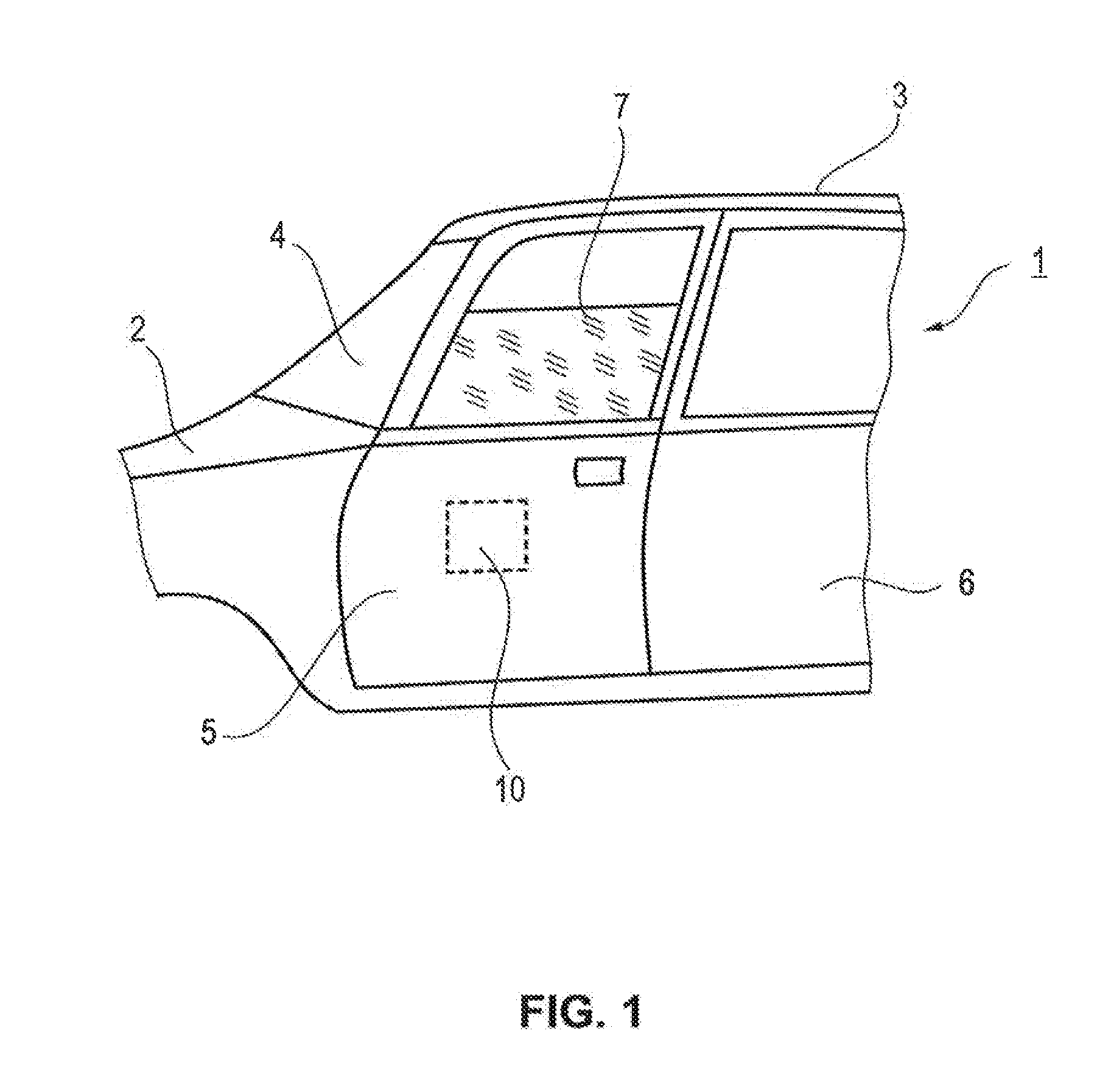
[0025]FIG. 1 is a schematic side view of a motor vehicle 1, of which the engine hood 2, the vehicle roof 3 and the windshield 4 can be seen. Furthermore, a front door (driver's door) 5 and a rear door (driver-side rear door) 6 can be seen. The front door 5 has an electrically driven vehicle window 7. A window lifter 10 which is indicated by dashed lines is usually mounted in the vehicle door (door module).

[0026]FIG. 2 shows the block diagram of a control circuit for the electric-motor-operated window lifter 10 which is referred to below as window lifter drive. The control circuit comprises a first switch or pushbutton key 11 for generating a closing instruction and a further switch or pushbutton key 12 for generating an opening instruction for the window lifter drive in order to close the vehicle window 7. The two switches 11, 12 are arranged in a switch housing or pushbutton key housing 13 into which a lighting element 14 of the control circuit is also suitably integrated. The ligh...


PUM


Abstract

The invention in certain embodiments relates to a control circuit for an electric-motor-operated window lifter (10) of a motor vehicle (1), the control circuit having a first switch (11) for opening a vehicle window (7), a second switch (12) for closing the vehicle window (7), and a control device (15), which, when one of the switches (11, 12) is activated, actuates the window lifter (10) to move the vehicle window (7) in the opening direction or closing direction. The control device (15) monitors the lighting current (ILED) which flows across a lighting element (14) for the switches (11, 12), and generates a control signal (I12), if appropriate, for opening the vehicle window (7) if the lighting current (ILED) exceeds an overcurrent threshold value (IRef) thereby detecting inundation of the vehicle.

Description

BACKGROUND[0001]1. Field of the Invention[0002]The invention relates to a control circuit for an electric-motor-operated window lifter drive of a motor vehicle, having a first and a second switch for opening and, respectively, closing a vehicle window, as well as having a control device, which, when the switches are activated, actuates the window lifter drive, and having a device for detecting inundation of the vehicle.[0003]2. Description of the Related Art[0004]A window lifter drive which is also referred to below as a window lifter and which is used to lift (close) and lower (open) a vehicle window in a motor vehicle usually comprises an electric motor which is generally coupled via a transmission gearing to the vehicle window and is actuated by means of an electronic control unit. For this purpose, a control device supplies pulses or signals to a relay circuit in the form of two individual relays or a double relay in order to energize the electric motor in opposing directions an...

Claims


Application Information

Patent Timeline
IPC IPC(8): E05F15/20B60J1/17H05B44/00
CPCB60R2021/0016E05Y2800/428E05Y2900/55E05F15/695G05B2219/37632G05B2219/45242G05B19/4061
Inventor DAIMINGER, RALFEBERLEIN, ANDREBAUMANN, SVEN
Owner BROSE FAHRZEUGTEILE GMBH & CO KG HALLSTADT (DE)
Learn More