Particulate matter detection sensor and particulate matter detection sensor unit

a technology of particulate matter and detection sensor, which is applied in the direction of instruments, heat measurement, machines/engines, etc., can solve the problems of increasing the conventional problem previously described, complex circuit configuration, and increasing the number of terminals, so as to reduce the total number of wires, reduce manufacturing costs, and simple structure

Active Publication Date: 2011-11-24
DENSO CORP
View PDF27 Cites 49 Cited by
  • Summary
  • Abstract
  • Description
  • Claims
  • Application Information

AI Technical Summary

Benefits of technology

[0018]Further, because the first state and the second state can be switched in the structure in which the switching means is placed on the conductive path of the pair of the detection electrodes, it is possible to use the same wires when the temperature of the sensor element is detected and the quantity of particulate matter is detected. This makes it possible to decrease the total number of wires in the particulate matter detection sensor connected to an electric control unit as the control device which receives detection signals transferred from the particulate matter detection sensor.
[0019]Accordingly, it is possible to provide the particulate matter detection sensor capable of detecting the quantity of particulate matter and the temperature of the sensor element with a simple structure and a low manufacturing cost and without increasing the total number of components.
[0021]In particular, the capacitor as the switching means in the particulate matter detection sensor prevents the DC current from flowing in the temperature detection resistance when receiving the DC signal, and on the other hand allows the AC current to flow through the temperature detection resistance when receiving the AC signal. The structure of the particulate matter detection sensor according to the present invention makes it possible to easily switch the first state and the second state in order to make the electrical connection and disconnection of the temperature detection resistance.
[0023]In general, because the capacitor as the switching means has relatively low heat resistance characteristics, deterioration and failure occur in the capacitor when it is placed in the exhaust gas pipe through which exhaust gas of a high temperature flows. Because the particulate matter detection sensor according to the present invention has the above structure in which the capacitor is placed at a position which is not affected from heat energy of the exhaust gas when the particulate matter detection sensor is placed in the exhaust gas pipe, it is possible to easily switch the first state and the second state and correctly detect the quantity of particulate matter and the temperature of the sensor element with high accuracy.
[0025]The particulate matter detection sensor according to the present invention further has a heater. When receiving electric power, the heater generates heat energy in order to heat the sensor element. In the particulate matter detection sensor, the heater generates heat energy when receiving electric power supplied from the electric power source under a control by a control means on the basis of the temperature of the sensor element detected in the second state. This makes it possible to adjust the temperature of the sensor element at the optimum temperature while monitoring the actual temperature of the sensor element, and to detect the quantity of particulate matter accumulated between the detection electrodes in the sensor element with high accuracy.
[0027]In the particulate matter detection sensor according to the present invention, because the temperature adjustment is executed to adjust the detected quantity of particulate matter accumulated between the detection electrodes which is calculated on the basis of the resistance value between the detection electrodes, it is possible to further increase the detection accuracy of detecting the quantity of particulate matter accumulated between the detection electrodes.

Problems solved by technology

This causes a complicated circuit configuration and increased number of terminals.
This increases the conventional problem previously described.

Method used


Image

  • Particulate matter detection sensor and particulate matter detection sensor unit
  • Particulate matter detection sensor and particulate matter detection sensor unit
  • Particulate matter detection sensor and particulate matter detection sensor unit

Examples


embodiment

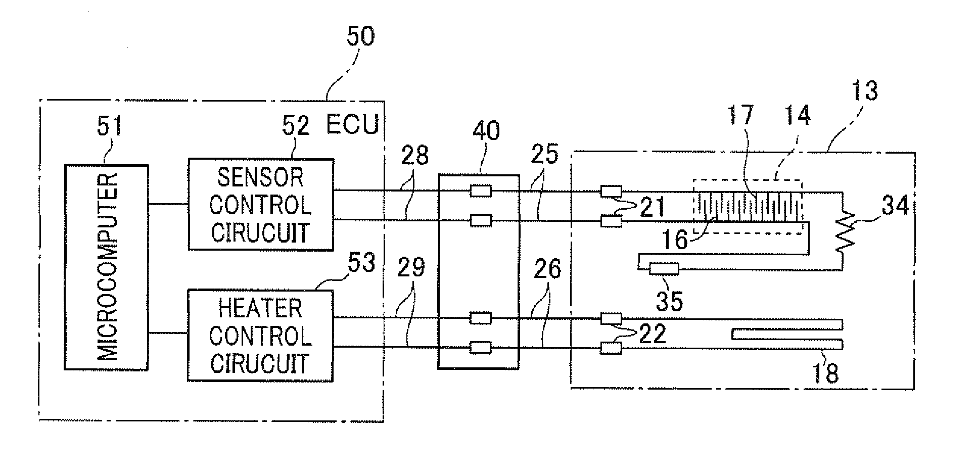
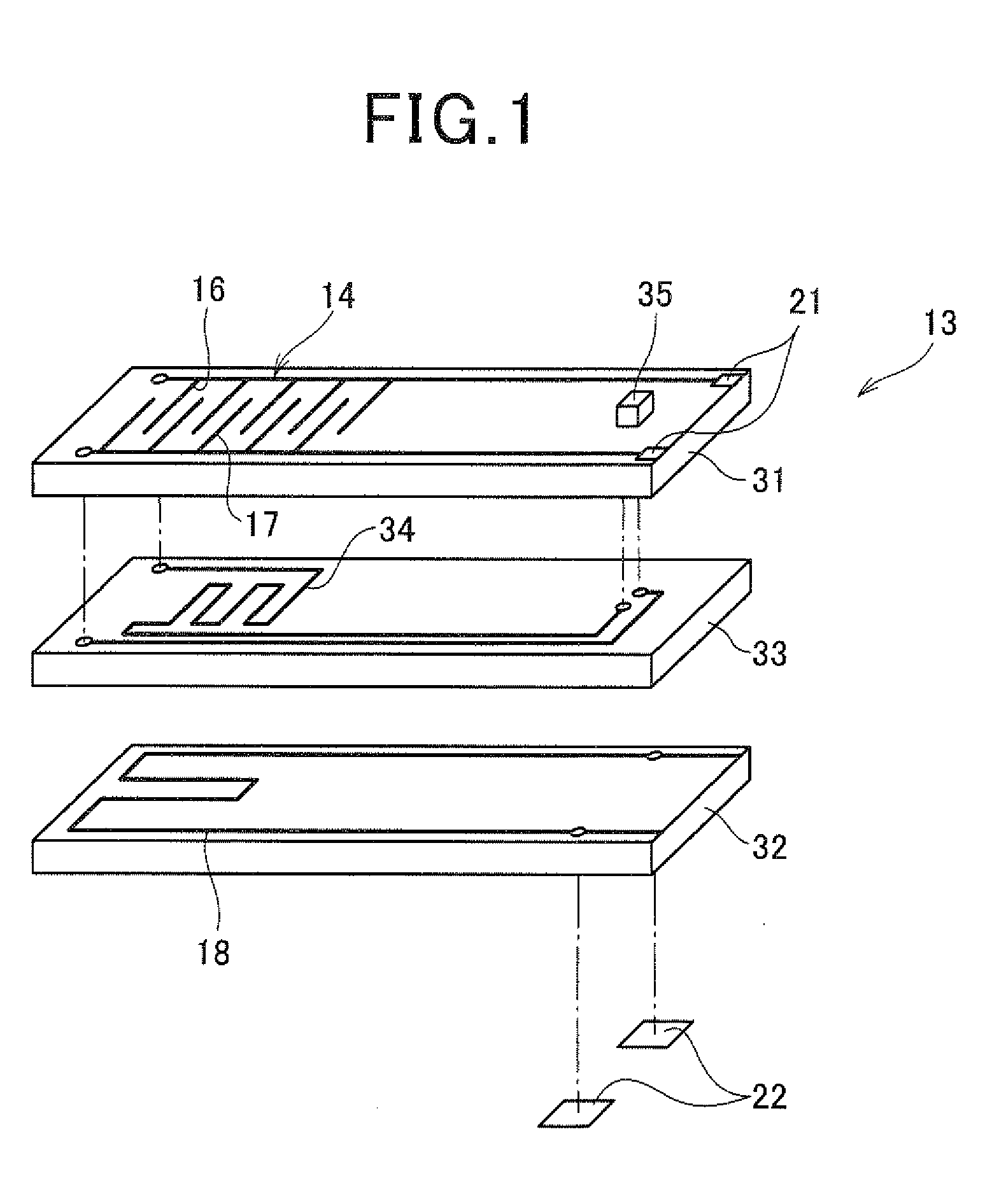
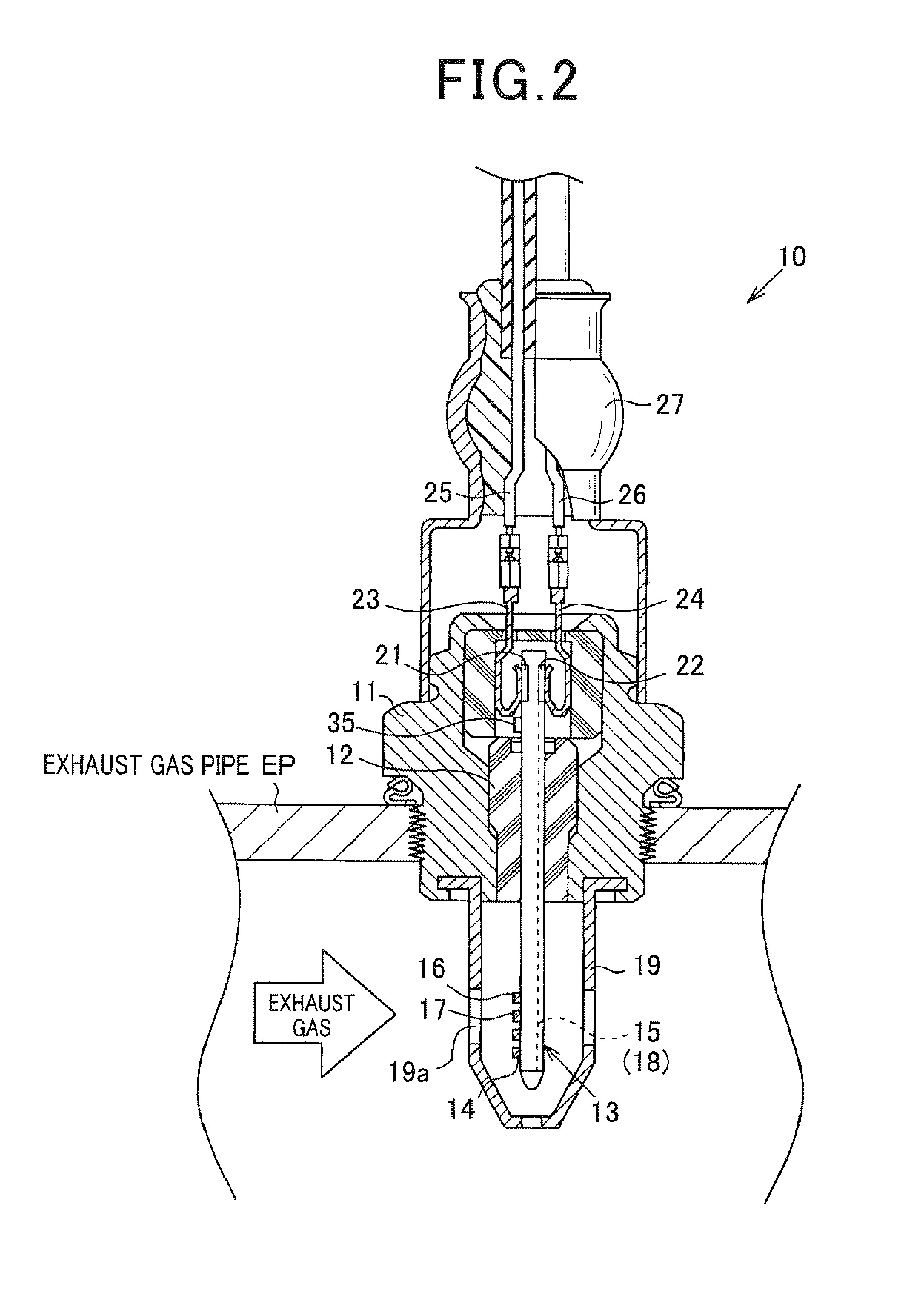
[0043]A description will be given of a sensor element 13, a particulate matter (PM) detection sensor 10, a PM detection sensor unit equipped with the PM detection sensor 10, and a PM detection sensor system according to an embodiment of the present invention with reference to FIGS. 1 to FIG. 9.

[0044]The particulate matter sensor system is mounted to an exhaust gas passage in an exhaust gas purifying system of an on-vehicle engine. The PM detection sensor system has the particulate matter detection sensor 10 according to the embodiment of the present invention. The PM detection sensor system has the PM detection sensor 10 in order to detect a quantity of conductive particulate matter (PM) contained in exhaust gas emitted from an on-vehicle engine. Such conductive particulate matter will also be referred to as the “particulate matter (PM)” in short.

[0045]For example, the on-vehicle engine is a diesel engine mounted to a motor vehicle. A diesel particulate filter (DPF) as the exhaust g...


PUM

PropertyMeasurementUnit
resistanceaaaaaaaaaa
DC voltageaaaaaaaaaa

Abstract

In a PM detection sensor with a sensor element having a pair of detection electrodes formed on a substrate, quantity of PM accumulated in the detection electrode is calculated on the basis of a resistance change between the detection electrodes. A series circuit composed of a temperature detection resistance and a capacitor connected in series is formed on a conductive path in the sensor element. A microcomputer in an ECU instructs a power source to supply a DC voltage to the resistance and the capacitor to make a first state in which no current flows in the resistance when a quantity of PM accumulated in the sensor element is detected. The microcomputer instructs the power source to supply an AC voltage to the resistance and the capacitor to make a second state in which a current flows in the resistance when a temperature of the sensor element is detected.

Description

CROSS-REFERENCE TO RELATED APPLICATION[0001]This application is related to and claims priority from Japanese Patent Application No. 2010-118837 filed on May 24, 2010, the contents of which are hereby incorporated by reference.BACKGROUND OF THE INVENTION[0002]1. Field of the Invention[0003]The present invention relates to particulate matter detection sensors and particulate matter detection sensor units capable of detecting a quantity of particulate matter contained in target detection gas such as exhaust gas emitted from an internal combustion engine.[0004]2. Description of the Related Art[0005]In general, a diesel engine exhaust gas system is equipped with a diesel particulate filter (DPF). Such a DPF can eliminate conductive particulate matter PM from exhaust gas emitted from a diesel engine. That is, the DPF captures particulate matter PM contained in exhaust gas. The particulate matter PM captured in the DPF is oxidized at a high temperature of the exhaust gas. In other words, t...

Claims


Application Information

Patent Timeline
Patent Type & Authority Applications(United States)
IPC IPC(8): G01N25/00
CPCF01N11/00F01N2560/20G01K7/16G01N15/0656G01K2013/024G01K2205/04G01K13/02G01K13/024
Inventor SUZUKI, TOSHIYUKI
Owner DENSO CORP
Why Eureka
Try Eureka