

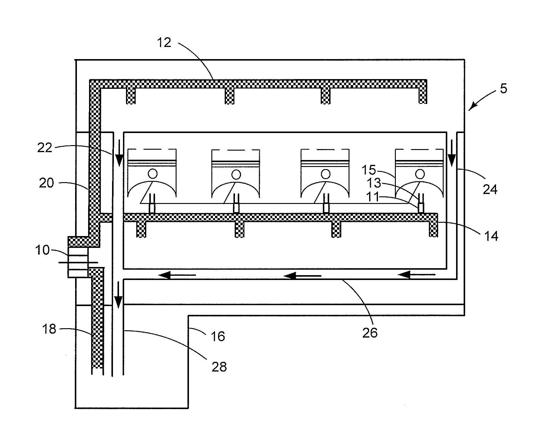
Oil supply system for an engine
a technology for oil supply systems and engines, applied in the direction of engine revolutions, lubrication of auxiliaries, crankcase compression engines, etc., can solve the problems of reducing fuel economy, oversupply of oil that uses unnecessary power, and negative effect on fuel economy, so as to reduce fuel consumption
- Summary
- Abstract
- Description
- Claims
- Application Information
AI Technical Summary
Benefits of technology
Problems solved by technology
Method used
Image

Examples
first embodiment
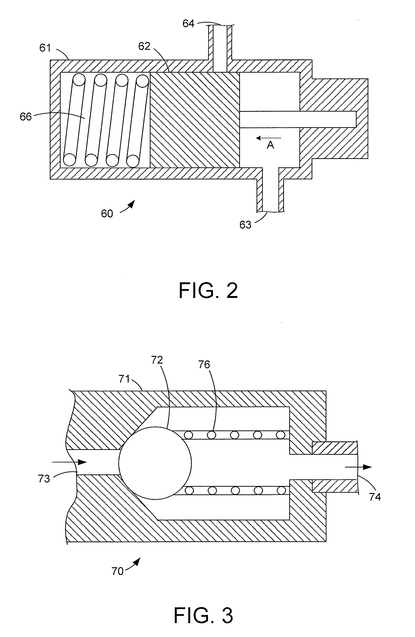
[0030]a pressure operated valve is shown in FIG. 2, where it can be seen that a pressure operated valve 60 has a housing 61 defining a cylindrical chamber in which is slidingly supported a piston 62. A spring 66 acts upon one end of the piston 62 so as to bias it into a valve closed position, as shown on FIG. 2. The piston 62 blocks an outlet 64 thereby preventing oil at pressure from passing through an inlet 63, through the pressure operated valve 60, to the outlet 64 and then on to one or more piston cooling jets (not shown). When the pressure in the inlet 63 exceeds a predetermined valve opening pressure, the pressure of the oil acting on the piston 62 is sufficient to displace the piston 62 against the action of the spring 66 thereby opening the flow of oil from the inlet 63 to the outlet 64 and allowing oil to flow to one or more piston cooling jets (not shown).
second embodiment
[0031]a pressure operated valve is shown in FIG. 3. A pressure operated valve 70 has a housing 71 defining a cylindrical chamber in which a valve member in the form of a ball 72 is slidingly supported. A spring 76 acts upon the ball 72 so as to bias it into a closed position as shown, where the piston ball 72 blocks an inlet 73, thereby preventing oil at pressure from passing through the pressure operated valve 70 to an outlet 74 and then on to one or more piston cooling jets (not shown). When the pressure in the inlet 73 exceeds a predetermined valve opening pressure, the pressure of the oil acting on the ball 72 is sufficient to displace it against the action of the spring 276, thereby opening the flow of oil from the inlet 73 to the outlet 74 and allowing oil to flow to one or more piston cooling jets (not shown). The application of a similar pressure operated valve is disclosed in US Patent publication 2010 / 0001103.
[0032]Referring now to FIGS. 4 to 9 the control of oil supply ci...
PUM
 Abstract
Description
Claims
Application Information