A steam cracking method

A technology of steam and cracking furnace, applied in the field of steam cracking, which can solve the problems of low thermal efficiency, high energy consumption and low selectivity

Active Publication Date: 2017-05-10
CHINA PETROLEUM & CHEM CORP +1
View PDF4 Cites 10 Cited by
  • Summary
  • Abstract
  • Description
  • Claims
  • Application Information

AI Technical Summary

Problems solved by technology

[0013] The purpose of the present invention is to overcome the problem of fuel consumption caused by air combustion and the mismatch between the radiation heat transfer of the cracking furnace furnace and the c

Method used


Image

  • A steam cracking method
  • A steam cracking method
  • A steam cracking method

Examples


Embodiment 1

[0055] This embodiment is to illustrate adopting the method of the present invention to carry out steam cracking.

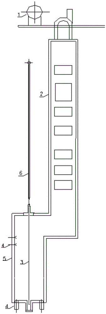
[0056] use figure 1 Shown steam cracking schematic diagram carries out cracking reaction, and concrete process comprises:

[0057] This method is implemented in the cracking furnace that contains blower fan 1 and quenching boiler 6, and described cracking furnace comprises convection section 2 and radiation section 5, and the cracking raw material naphtha of 60 ℃ enters after being vaporized and preheated through convection section 2 by convection section 2. The radiant furnace tube row 3 composed of two-pass radiant furnace tubes carries out the pyrolysis reaction, wherein the temperature at which naphtha is preheated in the convection section, that is, the crossover temperature (XOT) of the cracking furnace is 598°C, and the outlet temperature of the radiant section of the cracking furnace is 598°C. (COT) is 841°C;

[0058] Wherein, a radiant furnace tube row...

Embodiment 2

[0071] This embodiment is to illustrate adopting the method of the present invention to carry out steam cracking.

[0072] Steam cracking was carried out in the same manner as in Example 1.

[0073] The difference is:

[0074] The bottom burner supplies 80% of the total heat supply to the material in the tube row of the radiant furnace;

[0075] Oxygen-enriched air is used as the combustion-supporting gas, and the oxygen concentration contained in the oxygen-enriched air is 32% by volume (V / V).

Embodiment 3

[0086] This embodiment is to illustrate adopting the method of the present invention to carry out steam cracking.

[0087] Carry out steam cracking according to the same method as Example 1, the difference is that the bottom burner accounts for 85% of the total heat supply to the material in the tube row of the radiant furnace; oxygen-enriched air is used as the combustion-supporting gas, and The oxygen concentration contained in the oxygen-enriched air is 33% by volume (V / V);

[0088] Among them, the furnace tube in the radiant section adopts two-pass furnace tubes, and the first pass is two parallel vertical inlet pipes, and the second pass is a vertical outlet pipe, forming a 2-1 type radiant furnace tube, and the furnace tube The inlet diameter is 45mm, the outlet diameter of the furnace tube is 49.5mm, the length of the furnace tube is 12.8m, and the furnace tube adopts bottom-in and top-out; then the pyrolysis product is selectively collected through the quenching boiler...


PUM


Abstract

The invention relates to the field of chemical engineering and discloses a steam cracking method. The method is implemented in a cracking furnace. The cracking furnace includes a convection section and a radiation section. A radiation furnace tube row consisting of multiple-pass radiation furnace tubes is vertically disposed in the radiation section. Bottom combustors are disposed at the bottom of the radiation section. The method includes cracking a cracking raw material in the radiation section after the cracking raw material is gasified and preheated in the convection section. The multiple-pass radiation furnace tubes are furnace tubes having 2-4 passes. Oxygen-rich gas is adopted as combustion-supporting gas by the bottom combustors. The heat supplying amount of the bottom combustors for materials in the radiation furnace tube row is at least 60% of the total heat supplying amount. The furnace wall of the cracking furnace is an irregular structured furnace wall. Accordingly, the novel cracking method having characteristics of a proper running period, high selectivity, a high thermal efficiency and low energy consumption is obtained.

Description

technical field [0001] The invention relates to the field of chemical industry, in particular, the invention relates to a steam cracking method. Background technique [0002] Low-carbon olefins such as ethylene, propylene and butadiene are important basic raw materials for the petrochemical industry. At present, the method for producing low-carbon olefins is mainly based on the tube furnace petroleum hydrocarbon steam cracking process. According to statistics, about 99% of ethylene, more than 50% of propylene and more than 90% of butadiene in the world are produced through this process. [0003] The core equipment of the tubular furnace petroleum hydrocarbon steam cracking process is the tubular cracking furnace (hereinafter referred to as the "cracking furnace"). When the cracking raw materials such as ethane, propane, naphtha and hydrogenated tail oil are heated to high temperature in the cracking furnace , a carbon chain scission chemical reaction will occur to generate...

Claims


Application Information

Patent Timeline
IPC IPC(8): C07C4/04C07C11/04C07C11/06C07C11/16
CPCY02P20/10
Inventor 张利军王国清周先锋周丛刘俊杰杜志国张兆斌
Owner CHINA PETROLEUM & CHEM CORP
Why Eureka
Try Eureka