Brake device

a brake device and proportional solenoid technology, applied in the direction of brake systems, propulsion parts, transportation and packaging, etc., can solve the problems of reducing the service life of the brake device, so as to achieve sufficient braking force, high flow rate, and good responsiveness to sudden braking

Inactive Publication Date: 2011-11-24
ADVICS CO LTD
View PDF4 Cites 56 Cited by
  • Summary
  • Abstract
  • Description
  • Claims
  • Application Information

AI Technical Summary

Benefits of technology

[0007]The present invention has been made to solve the above problems, and it is an object of the present invention to provide a brake device capable of providing sufficient braking force in good responsiveness to sudden braking without causing the enlargement of the device and the increase of cost.
[0009]According to the brake device as described above, the desired pilot fluid pressure is generated in correspondence to an operating amount of the brake operating member or vehicle state by controlling the pressure boost control valve and the pressure reduction control valve of the electrically-operated pilot pressure generating part and is then input into the pilot pressure input port of the mechanical pressure regulating part. Thereby, the fluid pressure, which corresponds to the output fluid pressure of the electrically-operated pilot pressure generating part applied to the pilot pressure input port, is output from the output port of the mechanical pressure regulating part. Like this, the pressure boost control valve and the pressure reduction control valve having the relatively low flow rate per unit time are used to generate the pilot fluid pressure, which can sufficiently exhibit a function even when a flow rate thereof is low, thereby controlling the mechanical pressure regulating part that can output the relatively high flow rate (per unit time). As a result, it is possible to provide a brake device capable of providing sufficient braking force in good responsiveness to sudden braking without causing the enlargement of the device and the increase of cost.

Problems solved by technology

However, in general, flow rates per unit time of the proportional solenoid valves are relatively low.
Accordingly, when high braking force is abruptly required in braking a vehicle, a supply amount of the brake fluid for driving the master piston becomes smaller than a desired amount, so that the sufficient braking force may not be provided in good responsiveness to the braking.
However, in this case, the brake device would be enlarged and the cost would be increased.

Method used


Image

  • Brake device
  • Brake device
  • Brake device

Examples


Embodiment Construction

(1) First Illustrative Embodiment

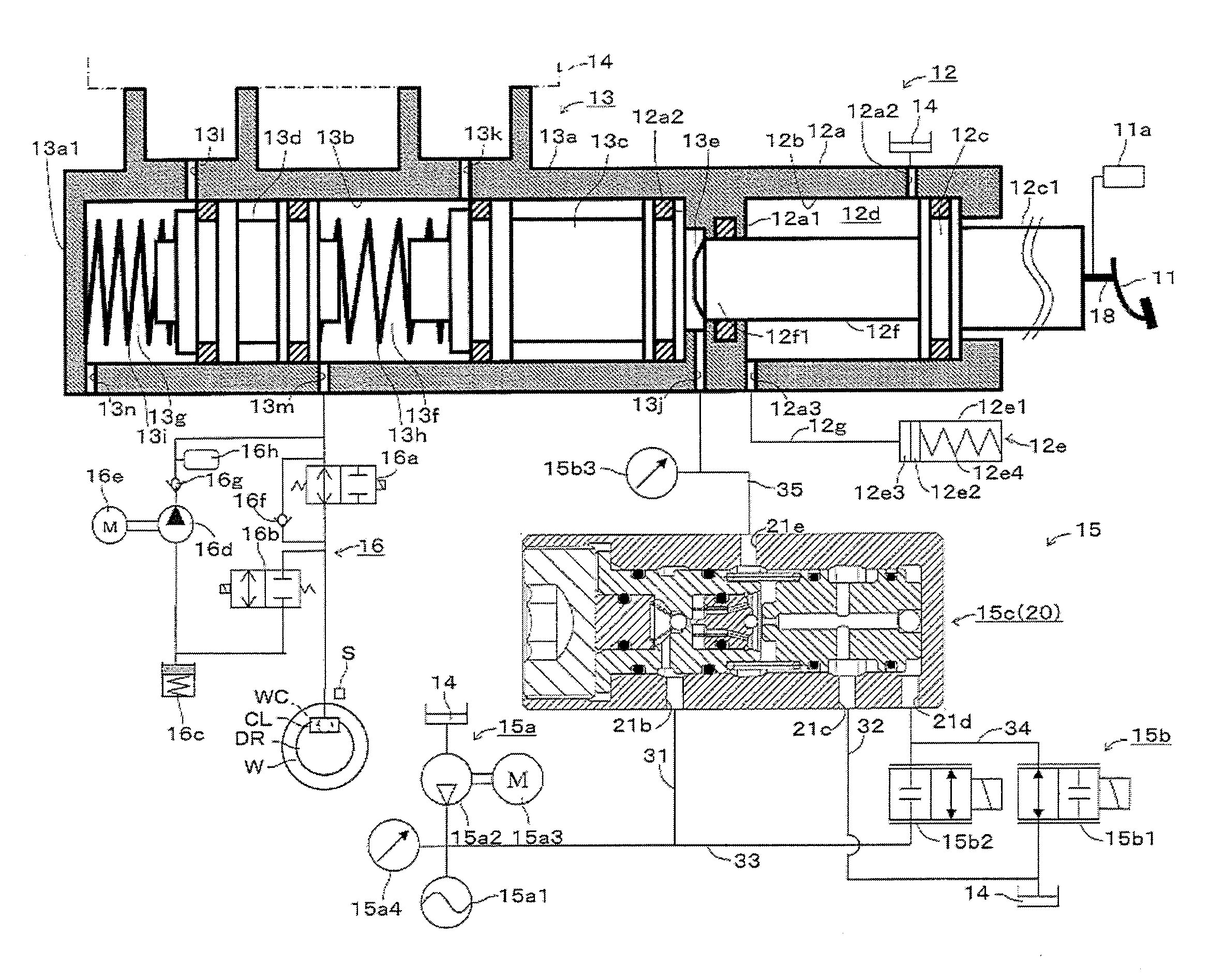
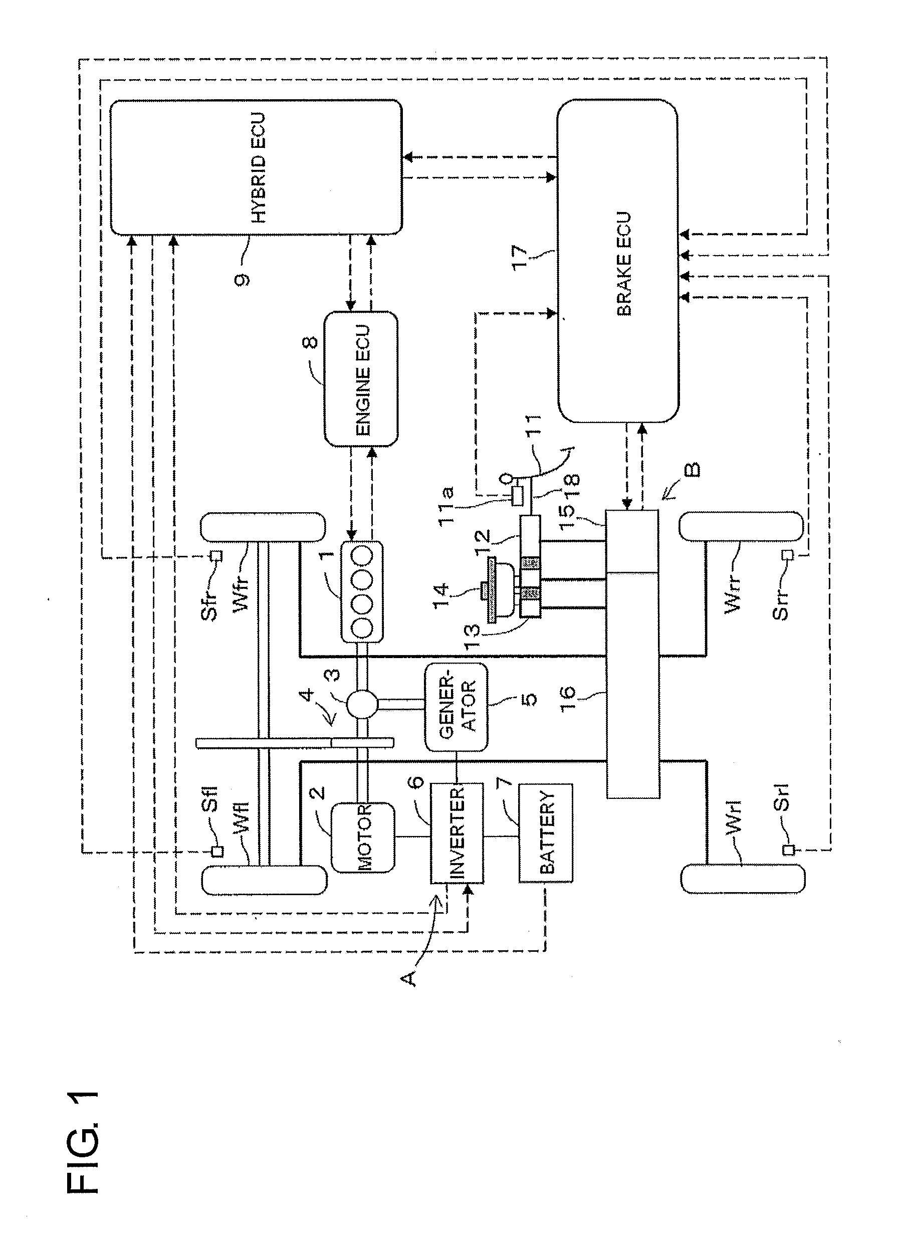
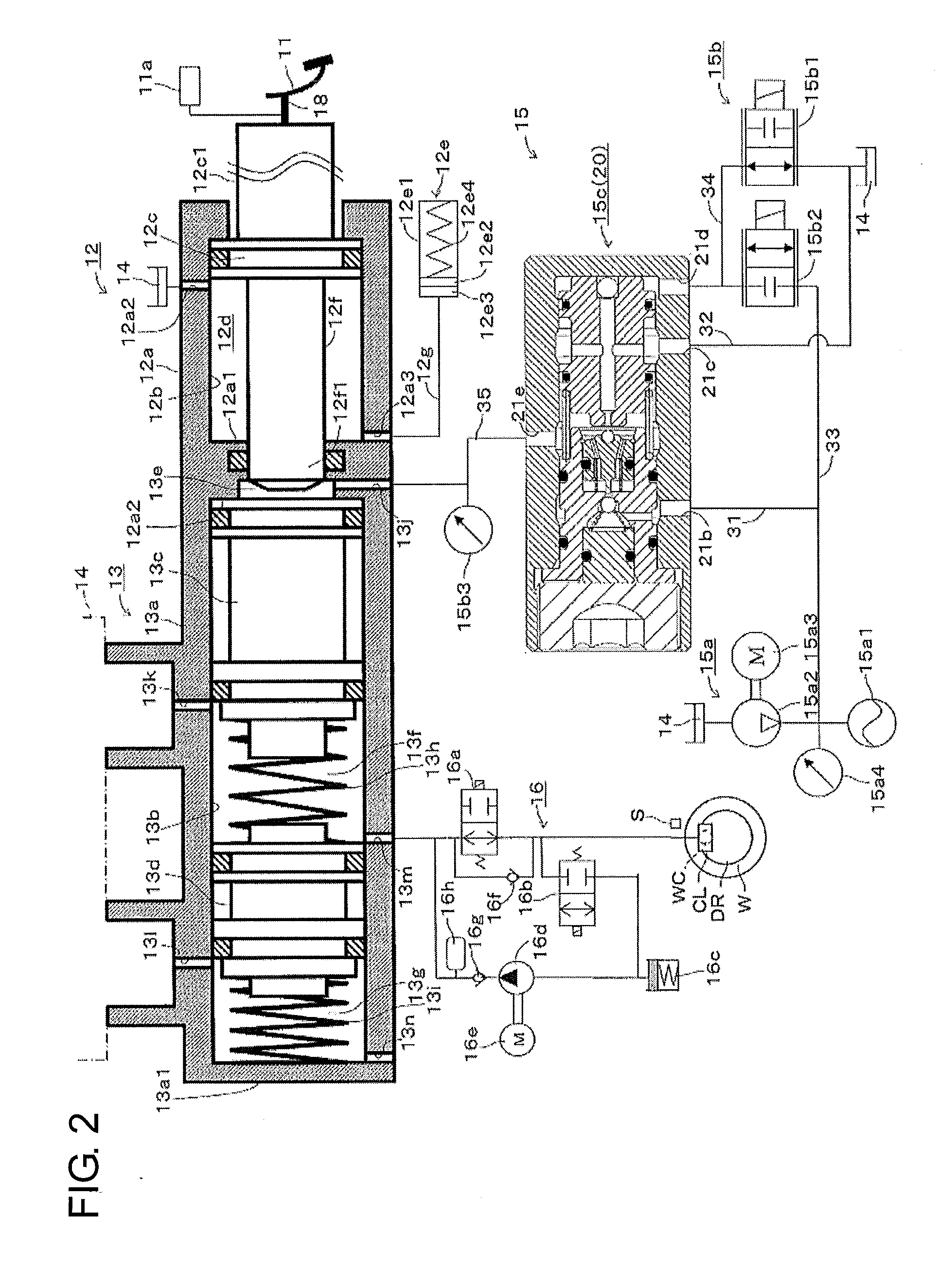
[0023]Hereinafter, a first illustrative embodiment where a brake device is applied to a hybrid vehicle will be described with reference to the drawings. FIG. 1 is an outline view showing a configuration of the hybrid vehicle, FIG. 2 is an outline view showing a configuration of the brake device and FIG. 3 is a sectional view showing a regulator that is a mechanical pressure regulating part.

[0024]As shown in FIG. 1, the hybrid vehicle is a vehicle that drives driving wheels, for example, left and right front wheels Wfl, Wfr by a hybrid system. The hybrid system has a power train that combines and uses two types of power sources, i.e., an engine 1 and a motor 2. In the first illustrative embodiment, the system is a parallel hybrid system that directly drives the wheels from the engine 1 and the motor 2. In the meantime, there is a series hybrid system in which the wheels are driven by the motor 2 and the engine 1 serves as a power supplying source to t...


PUM


Abstract

A brake device includes: a mechanical pressure regulating part having a high-pressure port, a low-pressure port, a pilot pressure input port, and an output port which outputs fluid pressure corresponding to the pressure supplied to the pilot pressure input port by fluid pressures supplied to both of the high- and low-pressure ports, to a chamber for a master piston; a high-pressure source connected to the high-pressure port and the pilot pressure input port; a low-pressure source connected to the low-pressure port and the pilot pressure input port; and an electrically-operated pilot pressure generating part which includes control valves for controlling flows of the brake fluid between the high-pressure source and the pilot pressure input port, and between the low-pressure source and the pilot pressure input port, respectively, and which outputs desired fluid pressure to the pilot pressure input port by controlling flow of the brake fluid with control valves.

Description

CROSS REFERENCE TO RELATED APPLICATIONS[0001]This application is based on and claims priority under 35 U.S.C.§119 to Japanese Patent Application 2010-116279, filed on May 20, 2010, the entire content of which is incorporated herein by reference.BACKGROUND[0002]1. Field of the Invention[0003]The present invention relates to a brake device.[0004]2. Description of Related Art[0005]JP-A No. 2007-182122 describes one type of brake devices. As shown in FIG. 1 of JP-A No. 2007-182122, the brake device has a driving fluid pressure chamber (external fluid pressure chamber 90p) that drives a master piston (rear master piston 62) and a pressure booster 90 that is connected to the driving fluid pressure chamber. The pressure booster 90 has a fluid pressure source 90a and a fluid pressure controller 90b, which are controlled by an electronic controller 13. The fluid pressure controller 90b has proportional solenoid valves 96a, 96b of a normally close type for pressure boost that are provided in ...

Claims


Application Information

Patent Timeline
Patent Type & Authority Applications(United States)
IPC IPC(8): B60T13/122B60T13/16B60T13/74
CPCB60T7/042B60T8/4077B60T13/145B60T13/686B60T13/161B60T13/58B60T13/745B60T11/103
Inventor ISHIDA, SATOSHI
Owner ADVICS CO LTD
Why Eureka
Try Eureka