Electromagnetic pump with oscillating piston

a technology of oscillating pistons and electric pumps, which is applied in the direction of electrical apparatus, positive displacement liquid engines, dynamo-electric machines, etc., can solve the problems of increasing the volume of the discharge chamber, the inlet valve of the discharge chamber cannot be opened, and the pressure in the discharge chamber is increased, so as to improve the guidance of field lines, improve the resulting electromagnetic force, and reduce the tolerance of the outside diameter of the piston

Active Publication Date: 2011-11-24
SAUERMANN IND
View PDF19 Cites 9 Cited by
  • Summary
  • Abstract
  • Description
  • Claims
  • Application Information

AI Technical Summary

Benefits of technology

The magnetic portion will preferentially consist of a magnetic ring, able to channel the field lines created by the magnets in order to limit the passage thereof in the air, which improves the resulting electromagnetic force.
Preferably a piston according to the ab

Problems solved by technology

This movement leads to an increase in the volume of the discharge chamber and reducing the pressure therein, which causes the non-return valve of the discharge chamber inlet to open.
This movement creates an increase in pressure in the discharge chamber, which leads to the closure of the inlet non-return valve and to the opening of the outlet non-return valve.
One of the drawbacks of these pumps of the prior art lies in low hydraulic performance—in particular throughput and suction.
Another drawback

Method used


Image

  • Electromagnetic pump with oscillating piston
  • Electromagnetic pump with oscillating piston
  • Electromagnetic pump with oscillating piston

Examples


Embodiment Construction

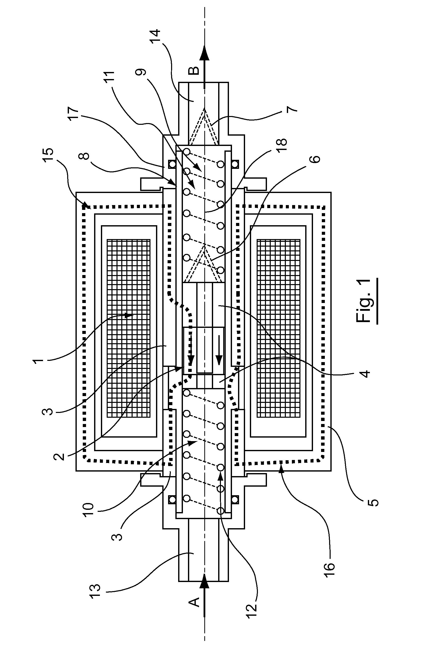
In the figures, the scales and proportions are not strictly complied with, for purposes of illustration and clarity.

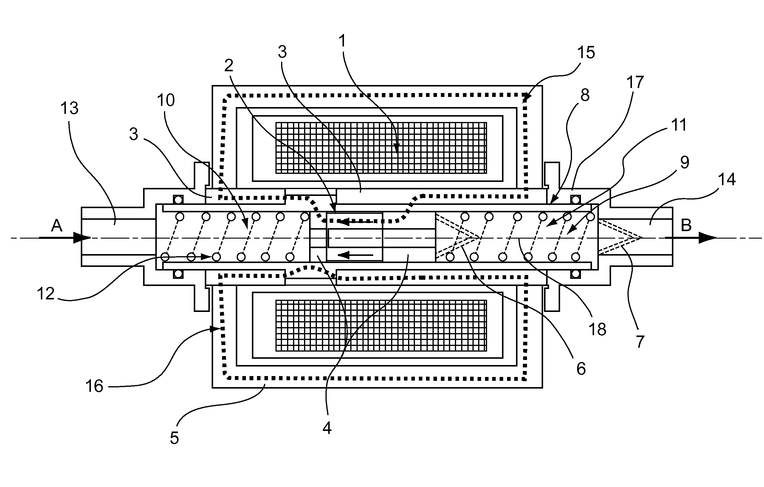
Throughout the detailed description that follows with reference to figures, the terms “upstream” and “downstream” are used with reference to the direction of flow of the fluid in the pump, when the latter is in operation. In FIGS. 1 and 3, the fluid enters the pump through the end 13 in the direction of the arrow A and leaves the pump through the end 14 in the direction of the arrow B. Thus the end 13 is an upstream end and the end 14 is a downstream end.

A pump according to an illustrative aspect of the disclosure comprises a hollow tubular body 8 extending along a longitudinal direction 18. This hollow tubular body 8 may be of any type. Preferably this body 8 is cylindrical with a circular base, with an axis of symmetry coinciding with the longitudinal direction 18.

The body 8 has on either side: a fluid entry 13 in the hollow tubular body 8, a fluid outlet 14 in the h...


PUM


Abstract

An electromagnetic pump is provided, which includes a hollow tubular body extending along a longitudinal direction, a piston mounted so as to be able to move inside the hollow tubular body, a solenoid, supplied with alternating current and assembled around at least a portion of the body and a magnetic envelope surrounding at least a portion of the body. The presence of a magnet magnetised longitudinally in a predetermined direction and a magnetic envelope orienting and channelling flux lines created by the magnet either around the solenoid or directly inside themselves creates an oscillating magnetic force on the piston.

Description

CROSS-REFERENCE TO RELATED APPLICATIONSNone.STATEMENT REGARDING FEDERALLY SPONSORED RESEARCH OR DEVELOPMENTNone.THE NAMES OF PARTIES TO A JOINT RESEARCH AGREEMENTNone.FIELD OF THE DISCLOSUREThe disclosure relates to pumping devices for lifting condensates, in particular in air conditioning systems, refrigeration systems, ventilation systems or heating systems.The disclosure more particularly relates to an electromagnetic fluid-pumping device for lifting condensates, comprising a magnetic piston oscillating under the effect of an electromagnetic field.BACKGROUND OF THE DISCLOSUREThroughout the text, a mechanical member will be said to be magnetic if the material that constitutes it has a relative magnetic permeability greater than 1. Such magnetic materials are for example ferromagnetic materials (iron, nickel, steel, cobalt, etc).A permanent magnet is a mechanical member that is magnetised permanently and itself generates a magnetic field.Electromagnetic pumps with an oscillating ma...

Claims


Application Information

Patent Timeline
IPC IPC(8): F04B17/04
CPCH02K33/16F04B17/046
Inventor SARDET, FRANCOIS
Owner SAUERMANN IND
Why Eureka
Try Eureka