
Sand and Dust Environmental Testing System

a technology of environmental testing and dust, which is applied in the direction of measurement devices, structural/machine measurement, instruments, etc., can solve the problems of failure to meet the requirements of environmental conditions, shorten the operational life of equipment, and fail to completely

Active Publication Date: 2011-12-01
AIR DYNAMICS INDAL SYST CORP
View PDF4 Cites 23 Cited by
  • Summary
  • Abstract
  • Description
  • Claims
  • Application Information

AI Technical Summary

Benefits of technology

"The invention is about an environmental testing system that can expose test pieces to particulate matter in an airflow. The system has a blower that creates the airflow and a particulate matter feed mechanism that injects particulate matter into the airflow. The system also has an exhaust fan and filter elements to create a negative pressure to remove particulate matter. The invention also includes a pneumatic conveying system to convey particulate matter into the system and a method to control the temperature and other test conditions during an environmental test. The technical effects of the invention are an improved environmental testing system that can accurately and safely test the performance of materials in a controlled environment."

Problems solved by technology

Equipment may also be subjected to environmental conditions such as rain, wind, sand, dust, and humidity, to name a few.
These environmental conditions can shorten the operational lifetime of a piece of equipment or cause it to fail entirely.
Test systems for performing sand or dust environmental testing do exist, but these systems do have a number of difficulties.
First and foremost, these systems can have difficulty producing a laminar airflow into the environmental testing chamber that has an even distribution of dust or sand particles, all of which are moving at essentially the same velocity.
Moreover, in some of these systems, the air mover or blower that creates the airflow into the test chamber is directly exposed to the sand or dust, which can cause wear and reduce the effectiveness of the blower.
Finally, sand and dust may be hazardous to human health.
Sand in particular can cause silicosis, a serious lung condition, if it is inhaled.

Method used


Image

  • Sand and Dust Environmental Testing System
  • Sand and Dust Environmental Testing System
  • Sand and Dust Environmental Testing System

Examples


Embodiment Construction

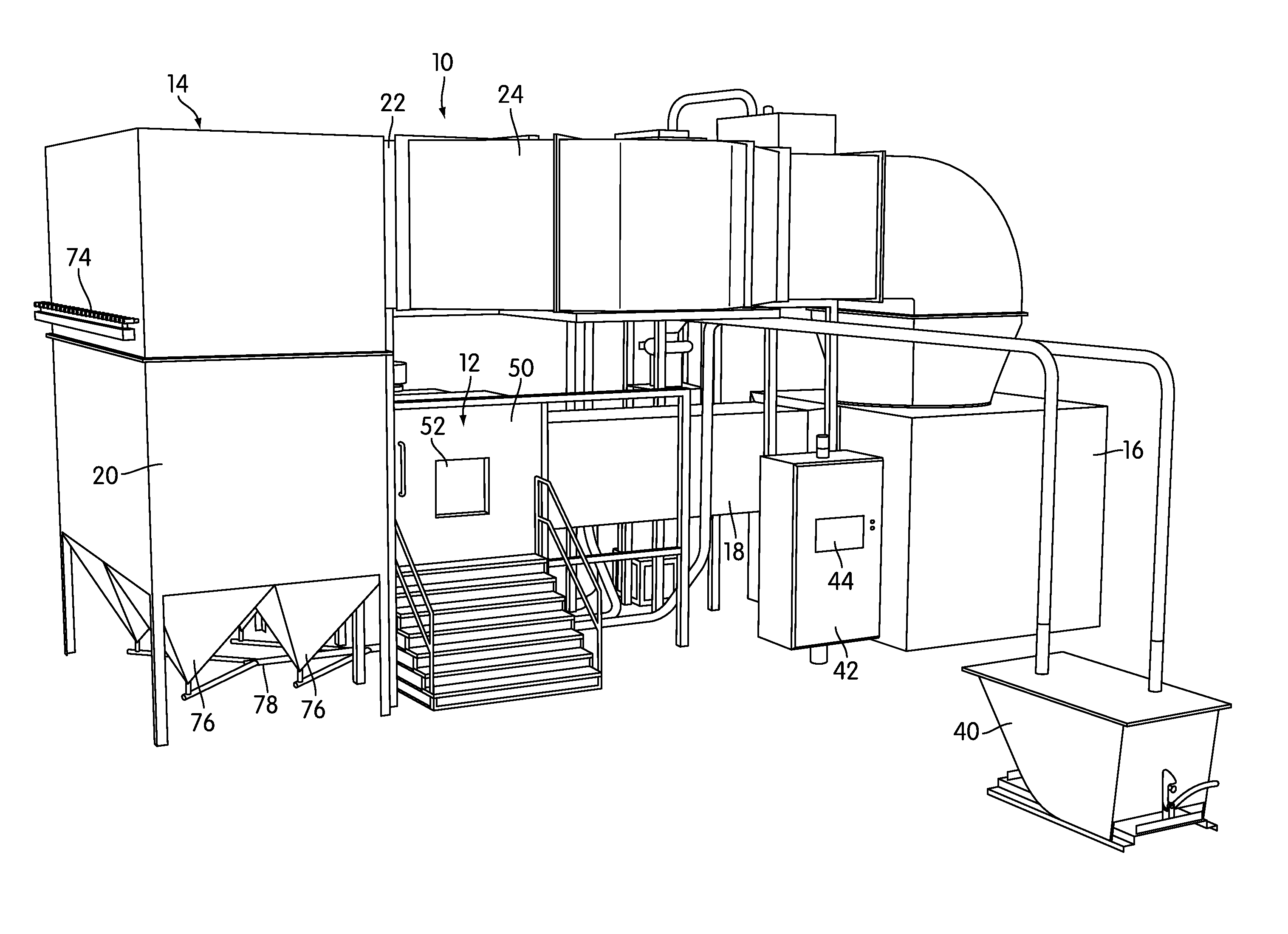
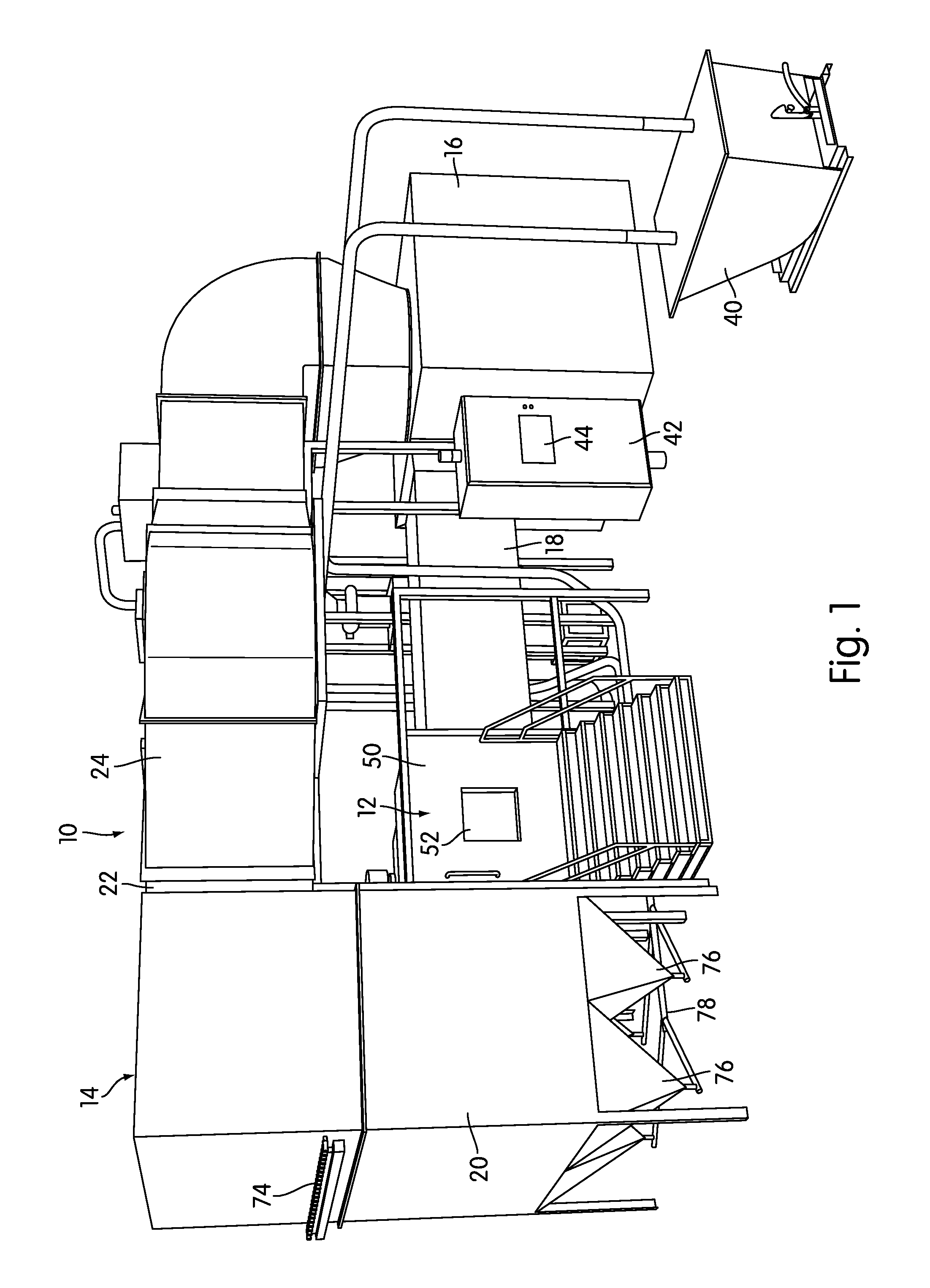
[0026]FIG. 1 is a front perspective view of a sand and dust environmental test system, generally indicated at 10, according to one embodiment of the invention. The testing system 10 is designed to expose a test piece to high-velocity airstreams with entrained sand or dust at elevated temperatures, in order to determine what effect those conditions have on the test piece. The testing system 10 may be constructed to perform tests according to recognized standards, such as the test methods set forth in MIL-STD-810G, although that need not necessarily be the case.

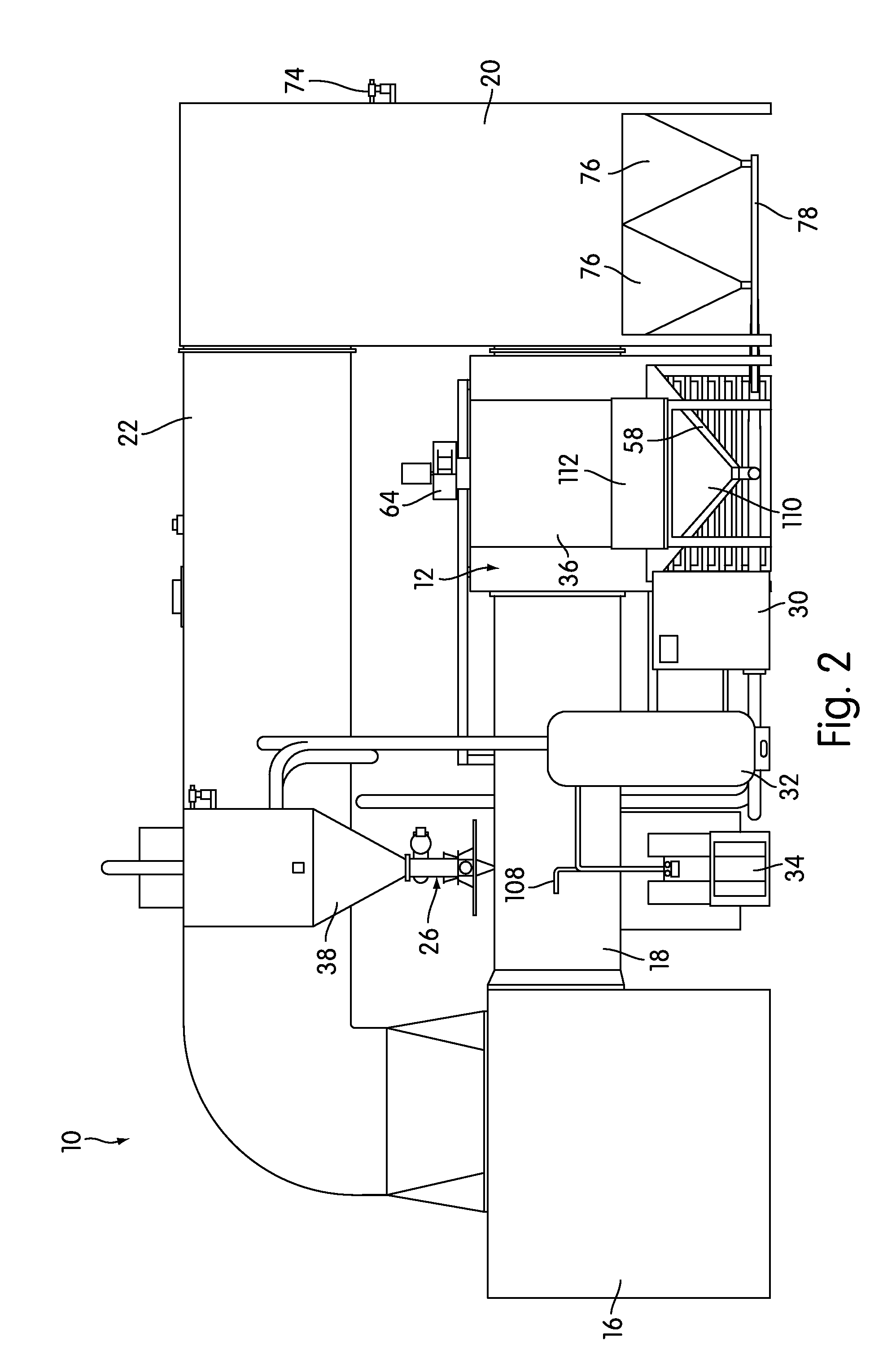
[0027]The testing system 10 includes an environmental chamber 12 into which the test piece (not shown in FIG. 1) is placed for testing. An air handling system, generally indicated at 14, creates the airflow necessary for the test, filters the particulate matter out of the air, and recirculates the air continuously during the test. The air handling system 14 comprises, among other components, a blower housing 16, where the blowe...


PUM

PropertyMeasurementUnit
temperatureaaaaaaaaaa
speedsaaaaaaaaaa
rated poweraaaaaaaaaa

Abstract

An environmental testing system for environmental testing with particulate matter, such as sand and dust, is disclosed. The testing system uses a feeder to feed precise amounts of particulate matter into an injector, which injects the particulate matter into the airflow leading to a test chamber with approximately the same velocity as the surrounding airflow. The feeder may be a loss-in-weight gravimetric feeder, and the injector may be a Venturi valve actuated by compressed air. The system also includes operator protection features, such as an exhaust fan that creates negative pressure when the door to the test chamber is opened, and when particulate matter is dumped into the system. A temperature control system heats and cools the airflow during tests, a pneumatic conveying system moves fluidized particulate matter into and out of the system, and a controller provides automatic control over the system.

Description

CROSS-REFERENCE TO RELATED APPLICATIONS[0001]This patent application claims priority to U.S. Provisional patent application No. 61 / 266,052, filed Dec. 2, 2009, the contents of which are incorporated by reference herein in their entirety.BACKGROUND OF THE INVENTION[0002]1. Field of the Invention[0003]The invention relates to environmental testing systems, and more particularly, to environmental testing systems capable of exposing a test piece to sand and dust.[0004]2. Description of Related Art[0005]Many pieces of equipment are subjected to environmental extremes during their service lifetimes. Those environmental extremes may be, for example, extremes of temperature, pressure, vibration, acceleration, or shock. Equipment may also be subjected to environmental conditions such as rain, wind, sand, dust, and humidity, to name a few. These environmental conditions can shorten the operational lifetime of a piece of equipment or cause it to fail entirely.[0006]Over time, various methods h...

Claims


Application Information

Patent Timeline
Patent Type & Authority Applications(United States)
IPC IPC(8): G01N17/00
CPCG01M99/002G01N17/002G01N17/02G01N3/56G01N3/567
Inventor LEHMAN, DANIEL P.LEHMAN, DANIEL A.
Owner AIR DYNAMICS INDAL SYST CORP
Learn More