
Installation for homogenization of temperature in an enclosure

a technology for installing and homogenizing temperature, which is applied in the direction of heating types, space heating and ventilation details, and domestic heating details, etc. it can solve the problems of forcing equipment to a high energy cost and consequent energy cost, and achieve the effect of preventing stratification

Inactive Publication Date: 2011-12-01
POLANCO MUNOZ RAFAEL
View PDF4 Cites 2 Cited by
  • Summary
  • Abstract
  • Description
  • Claims
  • Application Information

AI Technical Summary

Benefits of technology

[0003]Therefore, the object of the invention is achieved, at the minimal possible time and also with a minimal energy cost, the optimum comfort of a living space when cold air or hot air proceeding from a cooling equipment or heater is being applied to it.

Problems solved by technology

Therefore, as a consequence of that return air collection at the upper part, the produced cold reaches the lower zone when the equipment is operating as a cooling system, whereby the living space is further cooled at said lower zone, causing an environmental stratification in the living space itself, which forces the equipment to a high energy cost in order to equal the ambient temperature and disappear as far as possible such stratification, i.e. in order to achieve a comfortable environment in the entire living space.
If the equipment operates as a heating system, the same occurs but in reverse, i.e. the hot air which is driven by the grille placed at the upper part will firstly occupy the zone immediately bellow the ceiling, equally causing the stratification although in this case more stressed by the tendency of the hot air to rise, whereby the lower zone will be more cold and, the equipment should be operated more time than the one needed, with the consequent energy cost in order to achieve the comfort or temperature leveling between the upper and lower parts.

Method used


Image

  • Installation for homogenization of temperature in an enclosure
  • Installation for homogenization of temperature in an enclosure
  • Installation for homogenization of temperature in an enclosure

Examples


Embodiment Construction

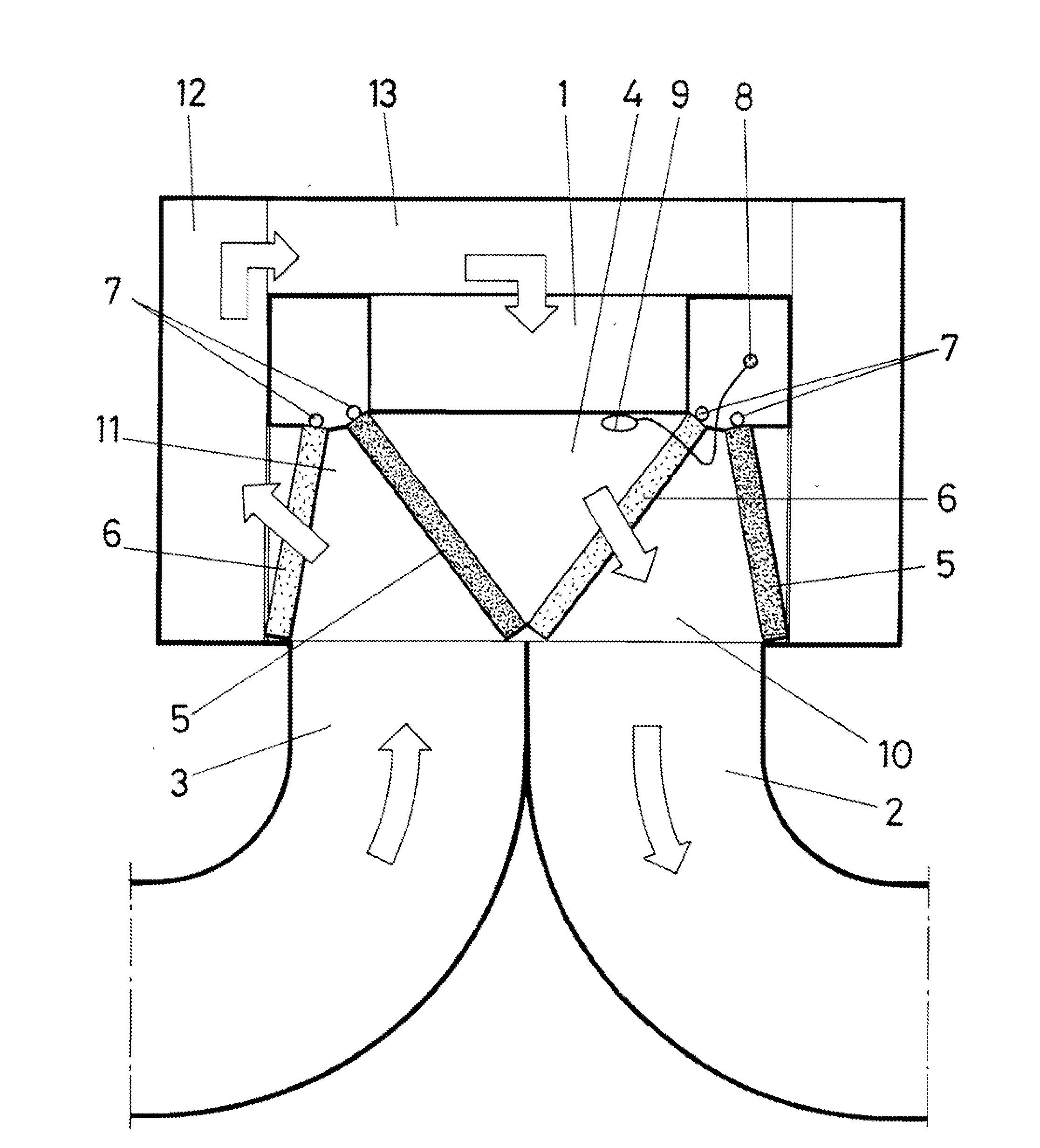
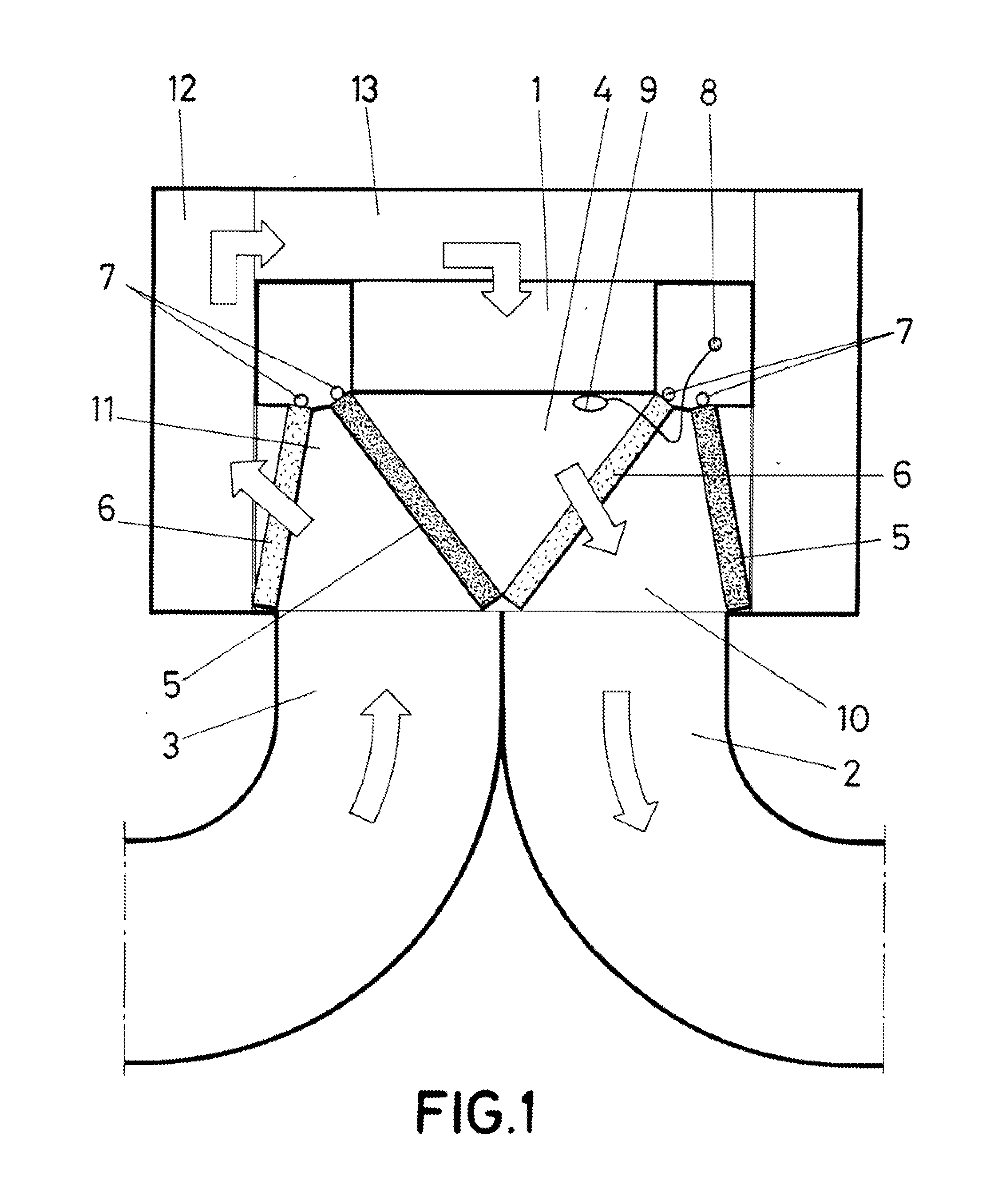
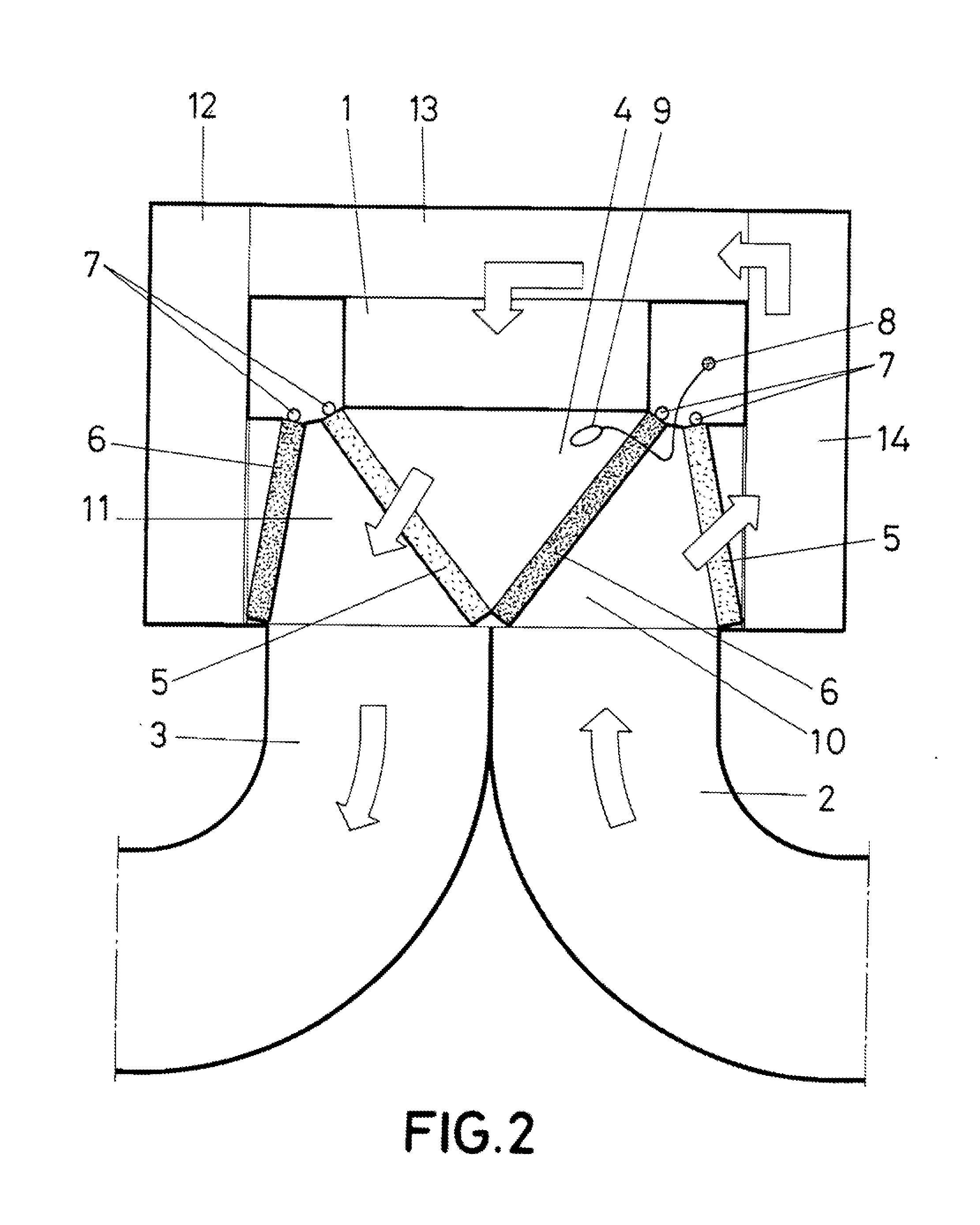
[0009]The installation object of the invention presents some peculiarities on which basis an optimum comfort for a living space in a minimal time, with air quality and without stratification, in either cooling operation or heating operation.

[0010]In such sense, the installation of the invention is characterized by comprising two ducts, one with a vent connected with the upper part and other with the vent connected with the lower part of the leaving space, all of this in such a way that the beginning of the ducts will be connected with the front part of the equipment for generating cold or heat.

[0011]On the other hand, it has been established that two couples of motorized grilles are mounted between said ducts and the equipment itself, which are placed for, depending on whether the equipment is operating for cold or operating for heat, establishing a canalization for vented air at the upper part and collection or return at the lower part, in the case of cold; or either establishing a...


PUM


Abstract

It has been forecasted for its mounting at the vent of an air conditioning equipment (1), and comprises two independent ducts (2 and 3), one of them with its vent at the upper part of the enclosure and the other with its vent at the lower part of the same enclosure. At the intersection zone between the equipment (1) and the ducts (2 and 3), two couples of grilles (5 and 6) capacitated for occupying two positions are mounted, in order to establish the respective canalizations (10 and 11) for directing cold air or hot air (depending on whether the equipment 1 is producing cold air or producing heat) toward the upper part of the duct (2) or toward the lower part of the duct (3), respectively, establishing is both cases the cold air or hot air return at the lower part of one or other duct.

Description

[0001]This Application is a continuation application of International Application PCT / ES2009 / 070536, filed Nov. 27, 2009, which is hereby incorporated by reference in its entirety.OBJECT OF THE INVENTION[0002]The present invention, as this specification states in its title, relates to an installation for homogenization of temperature in an enclosure, which has been conceived and made in order to prevent classical temperature stratification originated in an enclosure or living space when a cold air or hot air equipment is operating, which vents as well as its return are established at the upper part.[0003]Therefore, the object of the invention is achieved, at the minimal possible time and also with a minimal energy cost, the optimum comfort of a living space when cold air or hot air proceeding from a cooling equipment or heater is being applied to it.BACKGROUNDS OF THE INVENTION[0004]As it is known, cooling or heating systems or equipments, operated either in cold or heat, apply air ...

Claims


Application Information

Patent Timeline
Patent Type & Authority Applications(United States)
IPC IPC(8): F24F7/007G05D23/00F24F1/00
CPCF24F1/00F24F13/12F24F13/0236F24F1/0014F24F13/04
Inventor POLANCO MUNOZ, RAFAEL
Owner POLANCO MUNOZ RAFAEL
Learn More