Magnetically Actuated One-Way Clutch

Active Publication Date: 2011-12-01
FORD GLOBAL TECH LLC
View PDF6 Cites 50 Cited by
  • Summary
  • Abstract
  • Description
  • Claims
  • Application Information

AI Technical Summary

Benefits of technology

[0010]The one-way clutch provides a simple, reliable, low-cost selectable technique for controlling rotation of the rotor of a motor-generator. The clutch can be used in multiple applications where a magnetic field can be turned on and

Problems solved by technology

The generator's rotor exhibits unwanted rotation in some modes of operation.
Otherwise, th

Method used


Image

  • Magnetically Actuated One-Way Clutch
  • Magnetically Actuated One-Way Clutch
  • Magnetically Actuated One-Way Clutch

Examples


Embodiment Construction

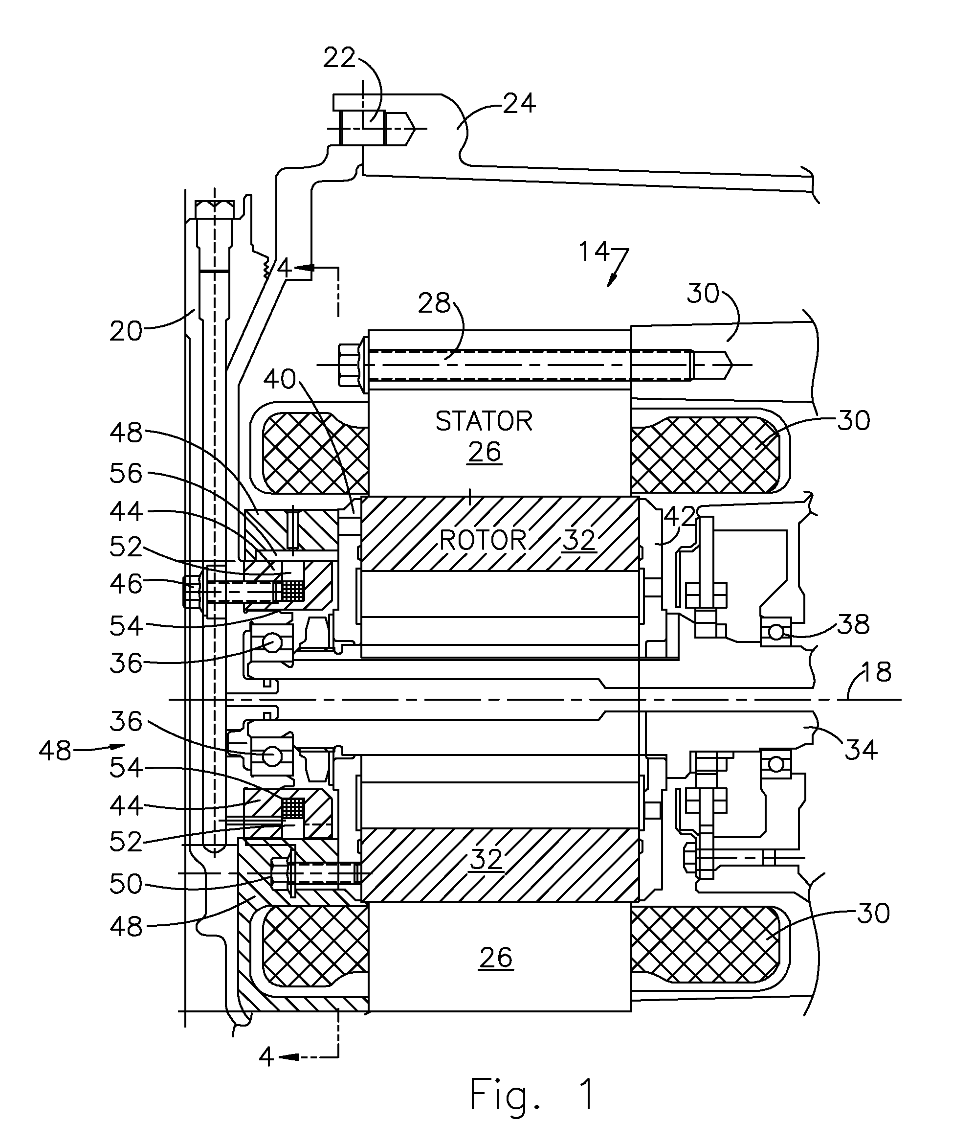
[0024]Referring now to the drawings, FIG. 1 shows a motor-generator 14 and one-way clutch 16 arranged about a central axis 18 and located within a space bounded by a front housing cover 20 secured by bolts 22 and to a housing 24, whose position is fixed.

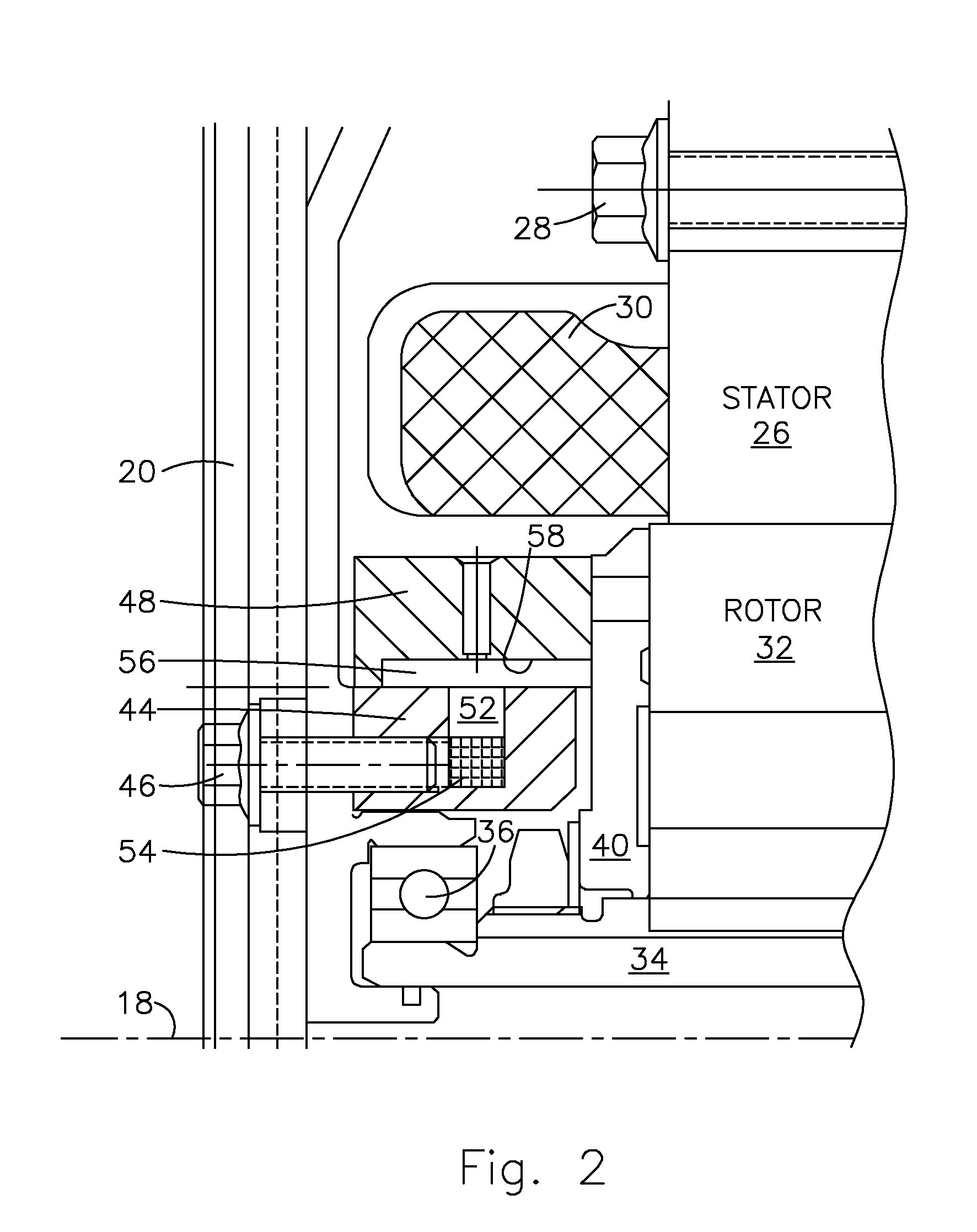
[0025]The motor-generator 14 includes a stator 26, secured by a series of bolts 28 to an extension of the housing 24 or another fixed member; electrically conductive wire wound in a coil 30 about axis 18; a rotor 32 surrounded by the stator; and a rotor shaft 34 supported for rotation about axis 18 on bearings 36, 38. Each axial end of the rotor 32 is covered by an end cap 40, 42.

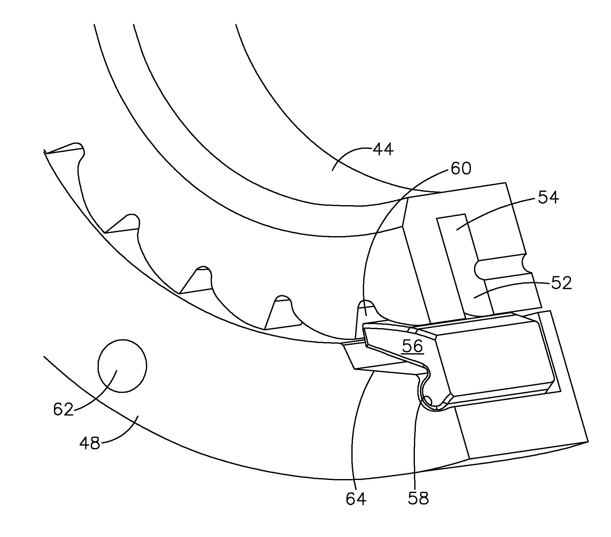
[0026]The one-way clutch 16 includes a cam plate or inner race 44, secured by a series of bolts 46 to housing cover 20; a pocket plate or outer race 48, secured by a series of bolts 50 to rotor 32; and struts or locking elements 56. The inner race 44 is formed with an annular groove 52 located mid-way between its axial ends. A toroidal coil 54 of electricall...


PUM


Abstract

A one-way clutch includes a first race secured against rotation and fitted with a coil, a second race supported for rotation, a coil carried by one of the races, and struts supported by one of the races, each strut driveably connecting and disconnecting the races in response to a magnetic field induced by current in the coil.

Description

BACKGROUND OF THE INVENTION[0001]1. Field of the Invention[0002]This invention relates generally to magnetically-actuated one-way clutch, and, more particularly to a motor-generator that employs a magnetically actuated one-way clutch especially for use in a hybrid electric vehicle.[0003]2. Description of the Prior Art[0004]The powertrain of a hybrid electric vehicle (HEV) includes an electric motor-generator. This generator is used to start the vehicle when in electric motor mode and when in generator mode the electric generator produces ac electric current, which is converted to dc and stored in an electric storage battery.[0005]Under certain vehicle operating conditions, the motor is used to drive the vehicle wheels. In other operating conditions the electric generator produces ac electric current, which is converted to dc and stored in an electric storage battery.[0006]The generator's rotor exhibits unwanted rotation in some modes of operation. The rotor must be stopped from rota...

Claims


Application Information

Patent Timeline
IPC IPC(8): F16D11/06F16D27/02F16D27/01
CPCF16D27/004F16D41/12F16D27/02F16D27/102
Inventor BIRD, NORMAN J.GARDNER, GREGORY D.JANSON, DAVID A.TRENT, MATTHEW T.
Owner FORD GLOBAL TECH LLC
Why Eureka
Try Eureka