Flow Adjusting Valve

a flow adjusting valve and flow adjusting technology, which is applied in the direction of valve operating means/releasing devices, functional valve types, transportation and packaging, etc., can solve the problems of drag, deformation of the valve orifice, and deterioration of the accuracy of the flow adjusting itself, so as to prevent the unnecessary operation of the needle valve, prevent the increase in the temperature of electrical equipment, and prevent the effect of unnecessary operation

Active Publication Date: 2011-12-01
SURPASS IND
View PDF12 Cites 4 Cited by
  • Summary
  • Abstract
  • Description
  • Claims
  • Application Information

AI Technical Summary

Benefits of technology

[0020]A flow adjusting valve according to a second aspect of the present invention includes a controller that stops the operation of the reciprocating movement section when the fully-closing valve piece is in the closed position; accordingly, an unnecessary operation of the needle valve is prevented.
[0021]In addition, in a flow adjusting valve according to a third aspect of the present invention, air is circulated in a space inside the casing, which accommodates electrical equipment; accordingly, ventilation cooling is performed and an increase in temperature of electrical equipment can be prevented. Furthermore, by performing the ventilation cooling, it is also possible to prevent an increase in temperature of electronic equipment in the casing and that of the fluid due to heat conduction.
[0022]With the present invention described above, a flow adjusting valve is formed having an integrated structure provided with a flow adjusting function and a flow-path blocking function; therefore, the installation space in an apparatus can be reduced while maintaining excellent flow reproducibility.

Problems solved by technology

With the open / close valves having such a flow adjusting function, it has been pointed out that precision of the flow adjustment itself deteriorates, that there is a problem with flow reproducibility due to changes in a valve seat shape, and that there is a problem with durability and strength because the motor is subjected to a piston load.
That is, when the needle valve is in close contact with the valve seat, the shape of the valve orifice is deformed due to drag, friction, etc.
; therefore, the original orifice shape (dimensions) cannot be maintained, and, as a result, accurate flow adjustment in accordance with the degree of opening (orifice shape) of the needle valve becomes difficult, causing the problem of the flow reproducibility.
However, when the flow adjusting valve and the open / close valve are installed in series, particularly when the open / close valve is connected next to the flow adjusting valve in a lateral series in a horizontal pipe, the footprints of the valves themselves, that is, spaces required for installing the valves, become large.

Method used


Image

  • Flow Adjusting Valve
  • Flow Adjusting Valve
  • Flow Adjusting Valve

Examples


Embodiment Construction

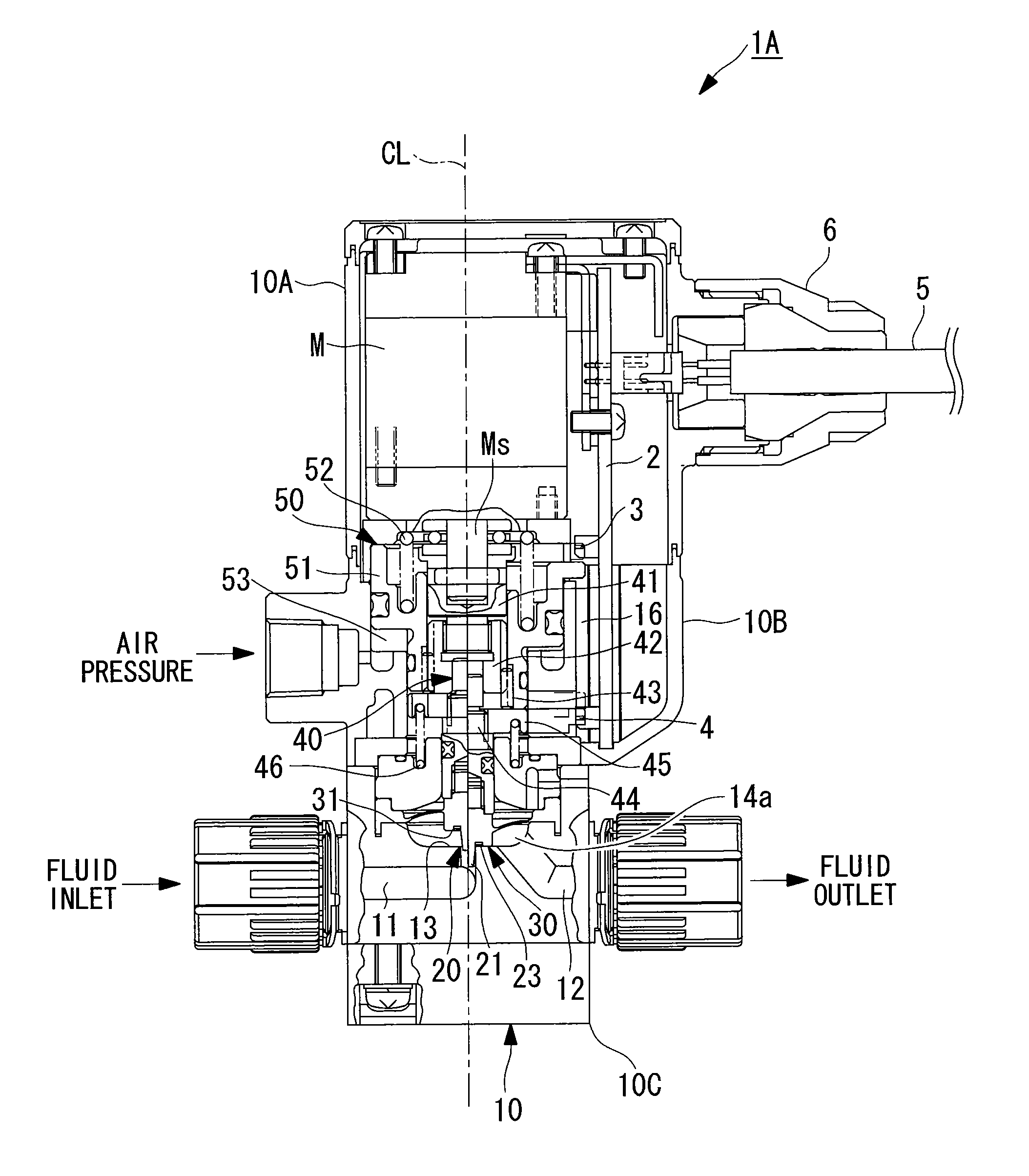
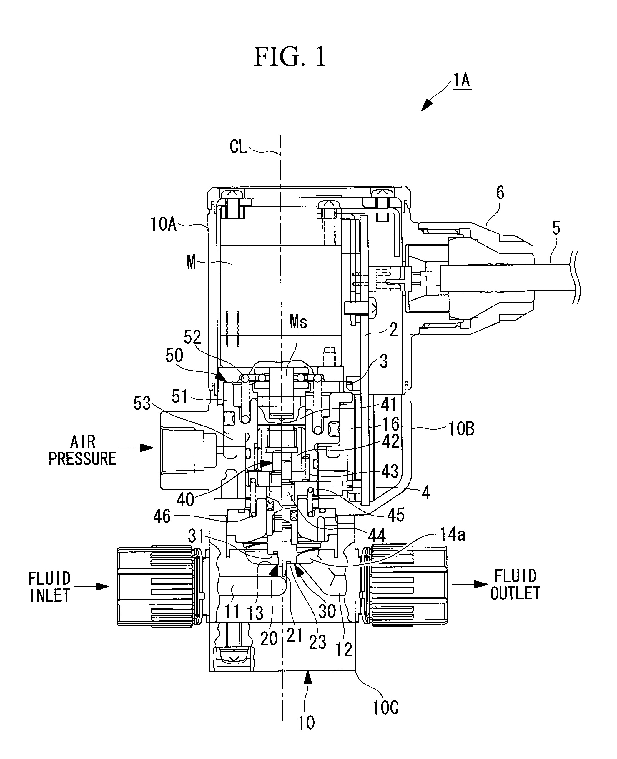
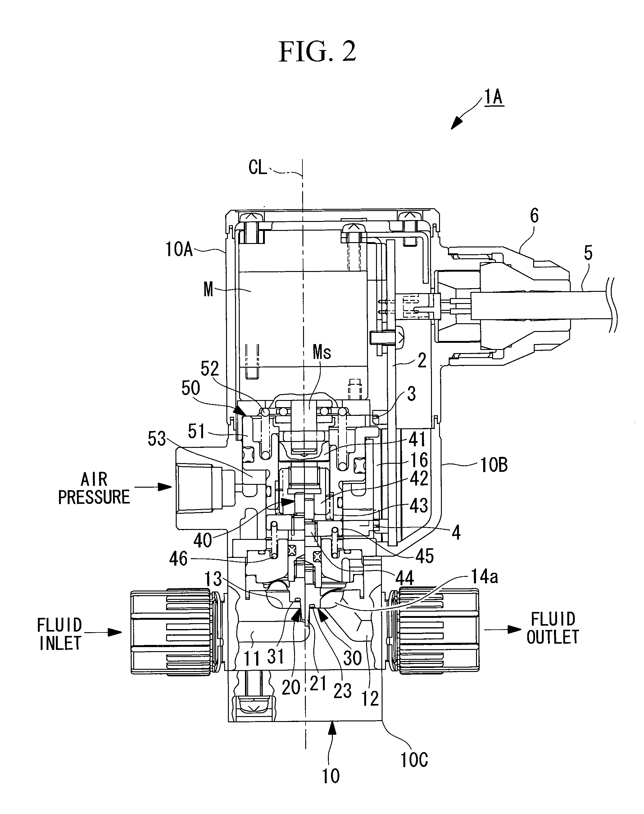
[0030]An embodiment of a flow adjusting valve according to the present invention will be described below on the basis of the drawings.

[0031]In this embodiment, descriptions will be given as applied to a flow adjusting valve that adjusts the flow of liquid fluid (chemical) in a semiconductor manufacturing apparatus; however, the flow adjusting valve of the present invention is not limited thereto, and it is also applicable to flow adjusting valves that adjust flows of liquid fluids in other apparatuses, etc.

[0032]In a flow adjusting valve 1A of the embodiment shown in FIGS. 1 to 4, a needle valve 20 that adjusts the flow of the liquid fluid and an open / close valve (shutoff valve) 30 that fully closes a flow path of the liquid fluid are accommodated inside a casing 10. In addition, this flow adjusting valve 1A is configured so that the degree of opening of the needle valve 2 is controlled by motion caused by employing a stepper motor (hereinafter, referred to as “motor”) M, and, furth...


PUM


Abstract

A needle valve that adjusts the flow of liquid fluid and an open/close valve that makes it possible to fully close a flow path of the liquid fluid are accommodated inside a casing of a flow adjusting valve. The needle valve is provided with a reciprocating movement section that adjusts the flow of the liquid fluid by moving a needle valve piece toward and away from the valve seat. The open/close valve is provided with an opening/closing section that utilizes a basal outer surface of the needle valve piece facing the valve seat as a fully-closing valve piece and that reciprocatingly moves the fully-closing valve piece, independently of the reciprocating movement section, between a closed position, where the fully-closing valve piece is in close contact with the valve seat, and an open position, where the fully-closing valve piece is moved away from the valve seat.

Description

CROSS REFERENCE TO RELATED APPLICATIONS[0001]This application claims benefit of Japanese Application No. 2010-122895 filed in Japan on May 28, 2010, the contents of which is hereby incorporated by its reference.BACKGROUND OF THE INVENTION[0002]1. Field of the Invention[0003]The present invention relates to a flow adjusting valve that is employed in a fluid transfer pipe used in various industrial fields, for example, chemical plants, semiconductor manufacturing, biotechnology, and so on, and that controls the flow of liquid fluid.[0004]2. Description of Related Art[0005]Known flow adjusting valves in the related art that adjust the flow of liquid, such as chemicals, etc., include those that employ a needle valve, as disclosed in Japanese Unexamined Patent Application, Publication No. 2006-153262. With such flow adjusting valves, remote control of the degree of opening of the needle valve has also been implemented by providing a stepper motor that rotationally drives a shaft piece an...

Claims


Application Information

Patent Timeline
Patent Type & Authority Applications(United States)
IPC IPC(8): F16K1/00
CPCF16K1/38F16K1/54F16K31/1221F16K31/047Y10T137/87137
Inventor HASUNUMA, MASAHIRO
Owner SURPASS IND
Why Eureka
Try Eureka