Eureka AIR delivers breakthrough ideas for toughest innovation challenges, trusted by R&D personnel around the world.

Vibration element, manufacturing method thereof, and vibration wave actuator

a technology of vibration actuator and manufacturing method, which is applied in the direction of mechanical vibration separation, generator/motor, piezoelectric/electrostrictive transducer, etc., can solve the problems of increasing manufacturing costs, affecting the efficiency of small vibration wave actuator, and relatively soft adhesive made of resin, so as to improve the efficiency of vibration and improve the bonding strength. , the effect of improving the efficiency of vibration

Inactive Publication Date: 2011-12-01
CANON KK
View PDF13 Cites 31 Cited by
  • Summary
  • Abstract
  • Description
  • Claims
  • Application Information

AI Technical Summary

Benefits of technology

[0015]The present invention is directed to a vibration element capable of outputting stable vibration energy by attempting to improve bonding strength between a piezoelectric element and a substrate with an inexpensive configuration and improving vibration efficiency by curbing vibration damping accompanying miniaturization, a manufacturing method thereof, and a vibration wave actuator.
[0019]According to an exemplary embodiment of the present invention, a vibration element capable of outputting stable vibration energy by attempting to improve bonding strength between a piezoelectric element and a substrate with an inexpensive configuration and improving vibration efficiency by curbing vibration damping accompanying miniaturization, a manufacturing method thereof, and a vibration wave actuator can be realized.

Problems solved by technology

However, an adhesive made of resin is relatively soft.
Thus, vibration damping of a vibration element is large and particularly an influence of the vibration damping of a vibration element increases with a decreasing size thereof, causing degradation of efficiency of a small vibration wave actuator as a leading factor.
Further, according to the manufacturing method of a conventional laminated piezoelectric element, the costs of plant and equipment investment of production units for green sheet formation from piezoelectric material powder, laminating press, machining and the like are large, contributing to increasing manufacturing costs as a factor.
However, a chemical reaction is normally less likely to occur between an electrode layer of a piezoelectric element and a ceramic substrate, resulting in comparatively low bonding strength between the electrode layer and the substrate.
Thus, the element may peel off from the substrate from the start or is more likely to peel off due to vibration.

Method used


Image

  • Vibration element, manufacturing method thereof, and vibration wave actuator
  • Vibration element, manufacturing method thereof, and vibration wave actuator
  • Vibration element, manufacturing method thereof, and vibration wave actuator

Examples


Embodiment Construction

[0028]Various exemplary embodiments, features, and aspects of the invention will be described in detail below with reference to the drawings.

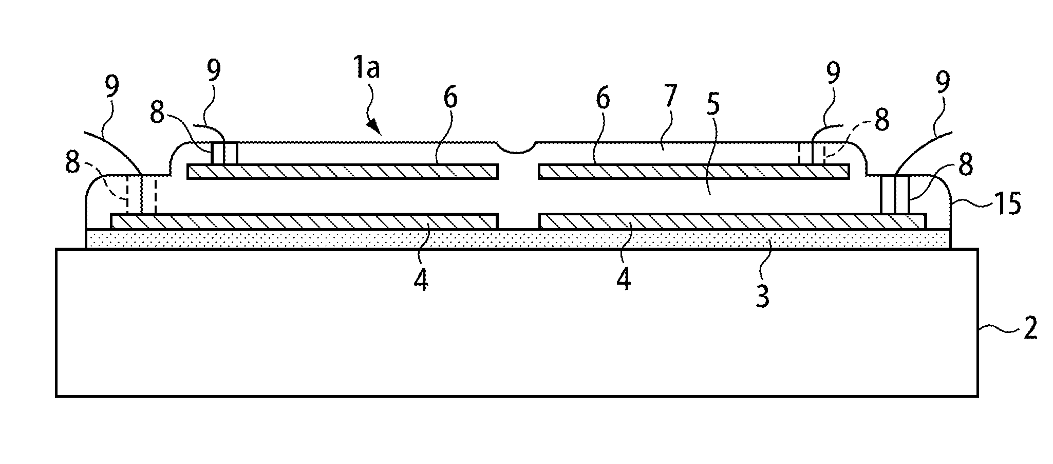
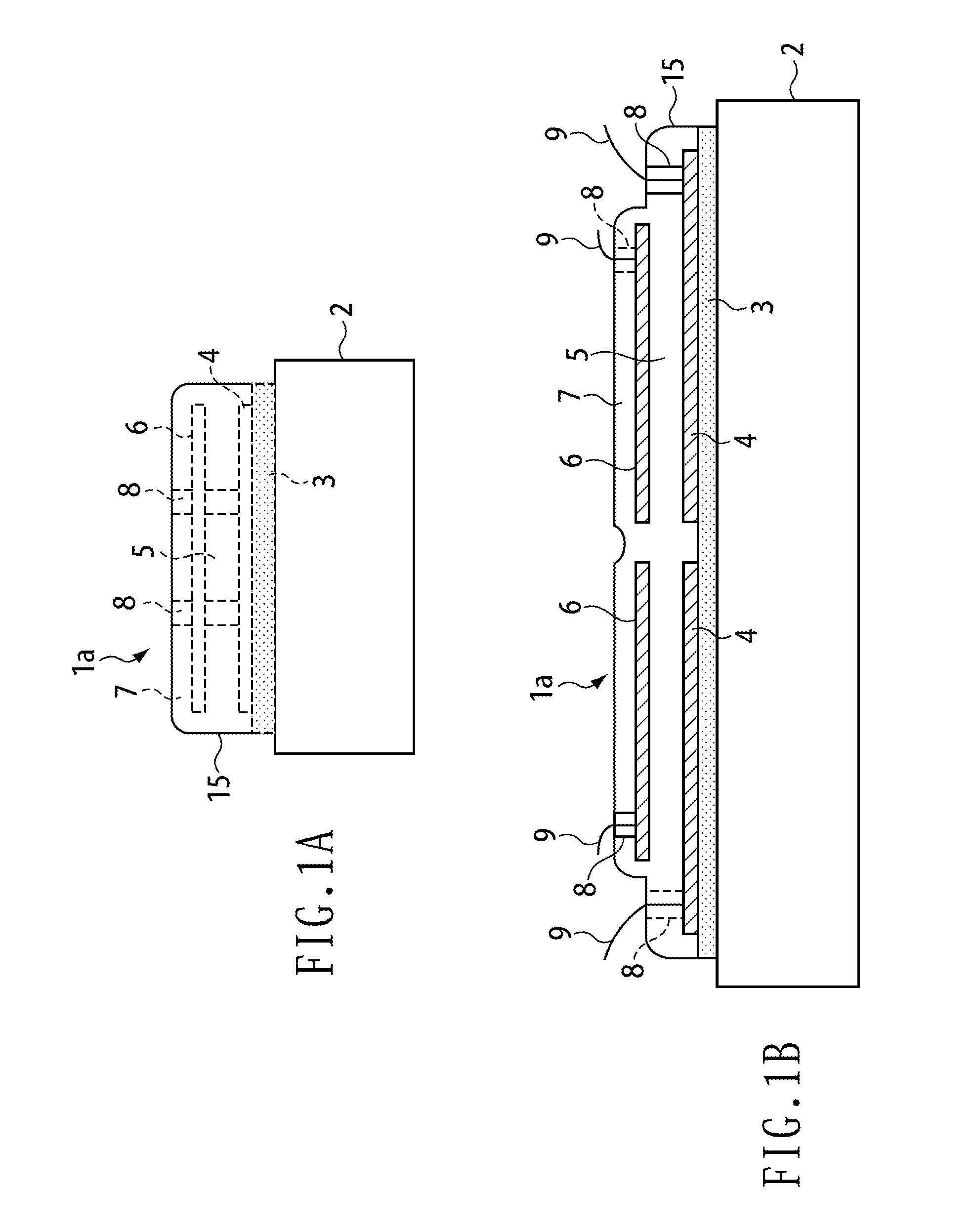
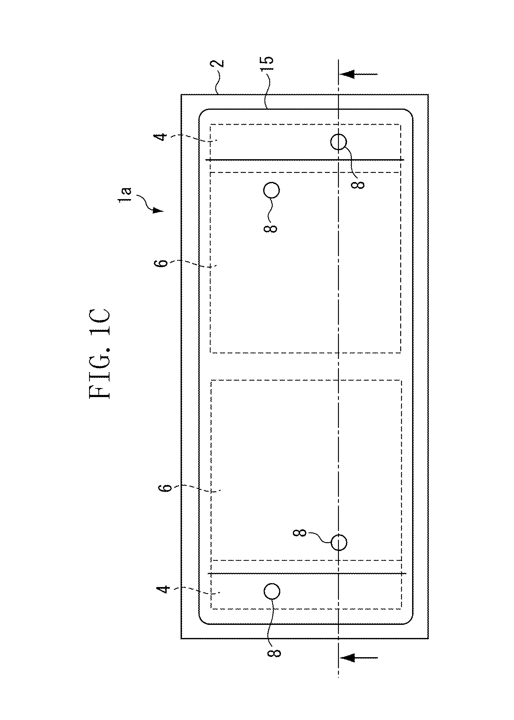
[0029]A configuration example of a vibration element according to a first exemplary embodiment of the present invention will be described with reference to FIGS. 1A to 1C. FIGS. 1A to 1C are a front view, a side view, and a plan view of the vibration element, respectively. FIG. 1B illustrates a section in a broken line position indicated by arrows in FIG. 1C.

[0030]A vibration element 1a illustrated in FIGS. 1A to 1C is assumed to be applied to a linearly driven vibration wave actuator. The vibration element 1a includes a substrate 2 in a plate shape, a piezoelectric element 15, and a bonding layer 3. As described below, the substrate 2 and the piezoelectric element 15 are bonded (fixed) and integrated by simultaneous sintering. That is, the piezoelectric element 15 functioning as a vibration energy source and the substrate 2 functioning as a vi...


PUM

PropertyMeasurementUnit
thicknessaaaaaaaaaa
thicknessaaaaaaaaaa
thicknessaaaaaaaaaa

Abstract

A vibration element includes a substrate, a piezoelectric element including a piezoelectric layer and an electrode layer, and a bonding layer provided between the piezoelectric element and the substrate and comprising ceramic containing melted glass powder, wherein the vibration element causes the substrate to vibrate by vibration energy of the piezoelectric element to output the vibration energy of the substrate, and the piezoelectric element is fixed to the substrate via the bonding layer.

Description

BACKGROUND OF THE INVENTION[0001]1. Field of the Invention[0002]The present invention relates to a vibration element in which a piezoelectric element is fixed onto a substrate, a manufacturing method thereof, and a vibration wave actuator using the vibration element.[0003]2. Description of the Related Art[0004]In a vibration wave actuator, a piezoelectric element has commonly been used as a vibration source of a vibration element. A single plate piezoelectric element, or a laminated piezoelectric element obtained by stacking many piezoelectric layers and then sintering formed / integrated layers, is used as the piezoelectric element. Particularly, compared with the single plate piezoelectric element, the laminated piezoelectric element has an advantage of being able to obtain a large deformation or a large force with a low applied voltage due to multi-layering (U.S. Pat. No. 7,109,639).[0005]FIG. 5 is a perspective view of appearance of a linear vibration wave (ultrasonic wave) actuat...

Claims


Application Information

Patent Timeline
Patent Type & Authority Applications(United States)
IPC IPC(8): H01L41/053H04R17/00B06B1/06H01L41/09H01L41/187H01L41/22H01L41/257H01L41/314H01L41/39H01L41/43H02N2/00
CPCH02N2/0015H02N2/026Y10T29/42H04R31/00H04R2440/00H04R17/00H10N30/074H10N30/079H10N30/85H02N2/001
Inventor MARUYAMA, YUTAKA
Owner CANON KK
Why Eureka
Eureka Blog
Learn More