Battery system and automobile

a battery system and battery technology, applied in the direction of battery/fuel cell control arrangement, secondary cell servicing/maintenance, electric devices, etc., can solve the problem of battery capacity decline, achieve efficient deactivation or inactivation, enhance the safety of lithium ion secondary batteries, and enhance the safety of automobiles

Active Publication Date: 2011-12-01
TOYOTA JIDOSHA KK
View PDF3 Cites 7 Cited by
  • Summary
  • Abstract
  • Description
  • Claims
  • Application Information

AI Technical Summary

Benefits of technology

[0009]In the above-described battery system, the temperature control device conducts control to maintain the temperature T of the lithium ion secondary battery mounted in the automobile as the drive power supply of the automobile within the range: 55° C.<T<65° C., for a predetermined length of time. If the temperature T of the lithium ion secondary battery is maintained at a higher temperature than 55° C. for a predetermined length of time, the metallic lithium deposited on the negative electrode of the lithium ion secondary battery can efficiently be deactivated or inactivated. By such deactivation or inactivation of the metallic lithium of high activity, it becomes possible to enhance the safety of the battery.
[0025]On the other hand, since the above-described automobile is provided with the aforementioned battery system, it is possible to efficiently deactivate or inactivate the metallic lithium deposited on the negative electrode of the lithium ion secondary battery while restraining the non-aqueous electrolyte from decomposition. It is therefore possible to enhance the safety of lithium ion secondary batteries, therefore eventually enhancing the safety of automobiles.

Problems solved by technology

Most of the lithium deposited on the negative electrode surface will make no contribution to the battery charging and discharging reaction, so that if such charging is repeatedly carried out, the problem arises that the battery capacity will decrease.

Method used


Image

  • Battery system and automobile
  • Battery system and automobile
  • Battery system and automobile

Examples


example 1

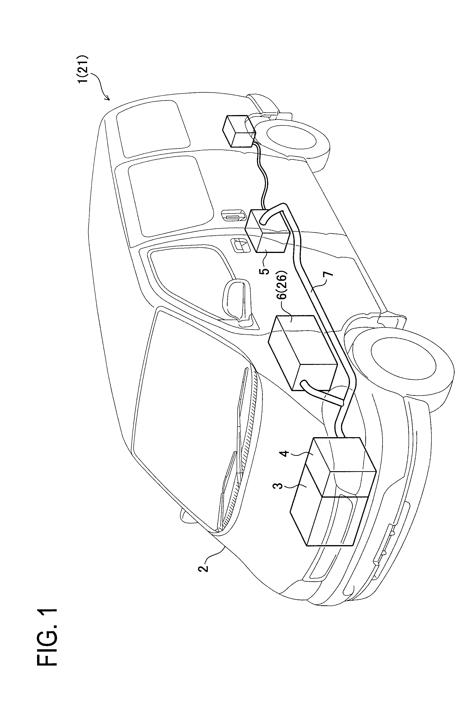
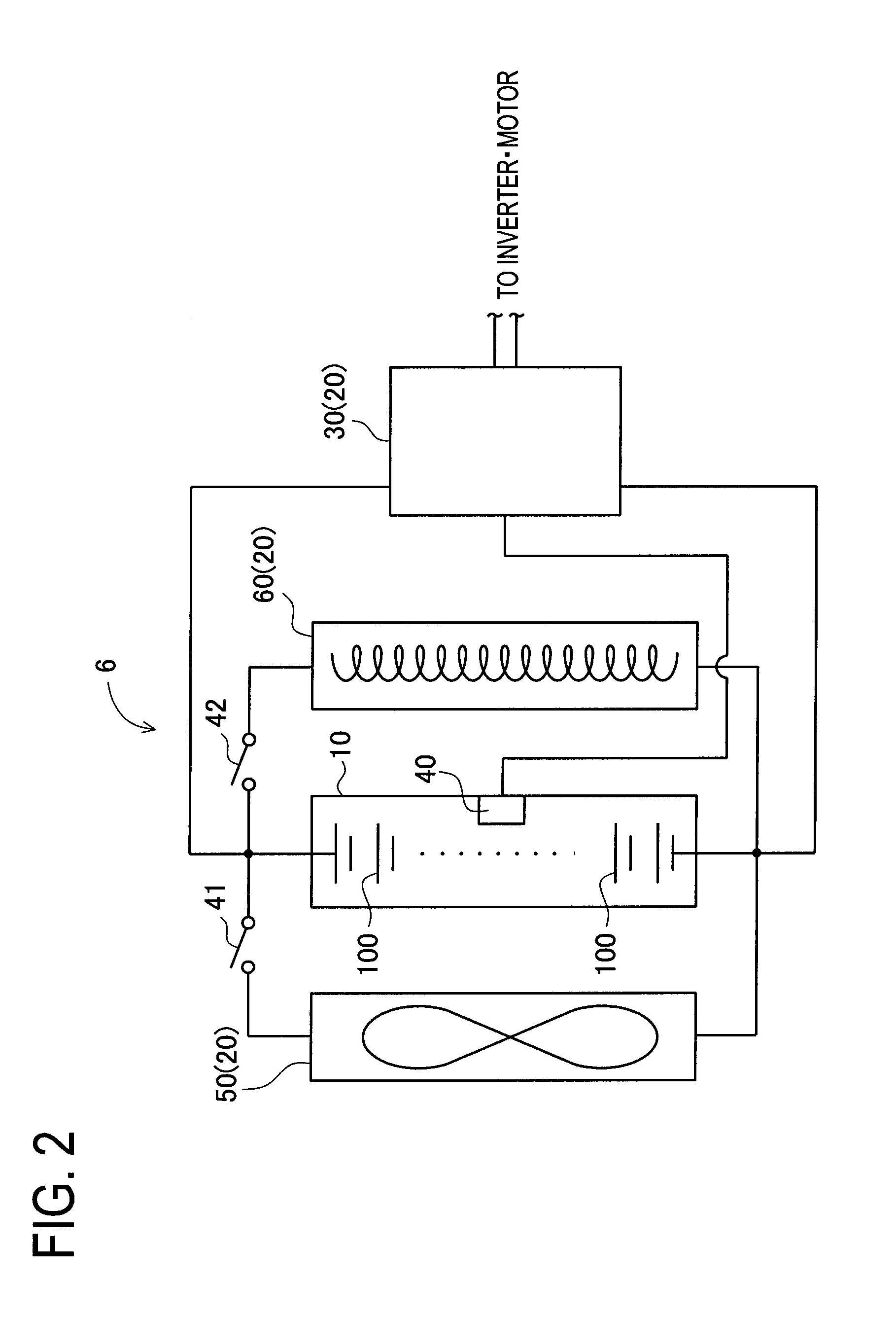
[0049]A detailed description of Example 1 embodying the present invention will now be given referring to the accompanying drawings. As shown in FIG. 1, an automobile 1 of Example 1 has a vehicle body 2, an engine 3, a front motor 4, a rear motor 5, a battery system 6 and a cable 7. The automobile 1 is a hybrid electric automobile which is driven by parallel use of the engine 3, the front motor 4 and the rear motor 5. In particular, the automobile 1 is configured such that it is driven by using the engine 3, the front motor 4 and the rear motor 5 by known means, with the battery system 6 (more specifically, an assembled battery 10 of the battery system 6, see FIG. 2) serving as a drive power supply for the front motor 4 and the rear motor 5.

[0050]Of these components, the battery system 6 is mounted to the vehicle body 2 of the automobile 1 and is connected by the cable 7 to the front motor 4 and the rear motor 5. As shown in FIG. 2, the battery system 6 is provided with the assembled...

example 2

[0091]Next, a description will be given regarding Example 2 of the present invention referring to the drawings. A hybrid electric automobile 21 of Example 2 is shown in FIG. 1. This hybrid electric automobile 21 differs from the hybrid electric automobile 1 of Example 1 only in a battery system. As shown in FIG. 8, a battery system 26 of Example 2 is provided with an assembled battery 10 which is of the same type as that of Example 1 and a temperature control device 320 which is different from that of Example 1. The temperature control device 320 has a cooling device 50 and a heating device 60, both of which are of the same type as those of Example 1, and a microcomputer 330 which is different from that of Example 1. The microcomputer 330 has a ROM, a CPU, a RAM etc. which are not shown in the figure.

[0092]The microcomputer 330 first judges whether or not the battery temperature T of the lithium ion secondary battery 100 detected through the thermistor 40 is 45° C. And, if the micro...

example 3

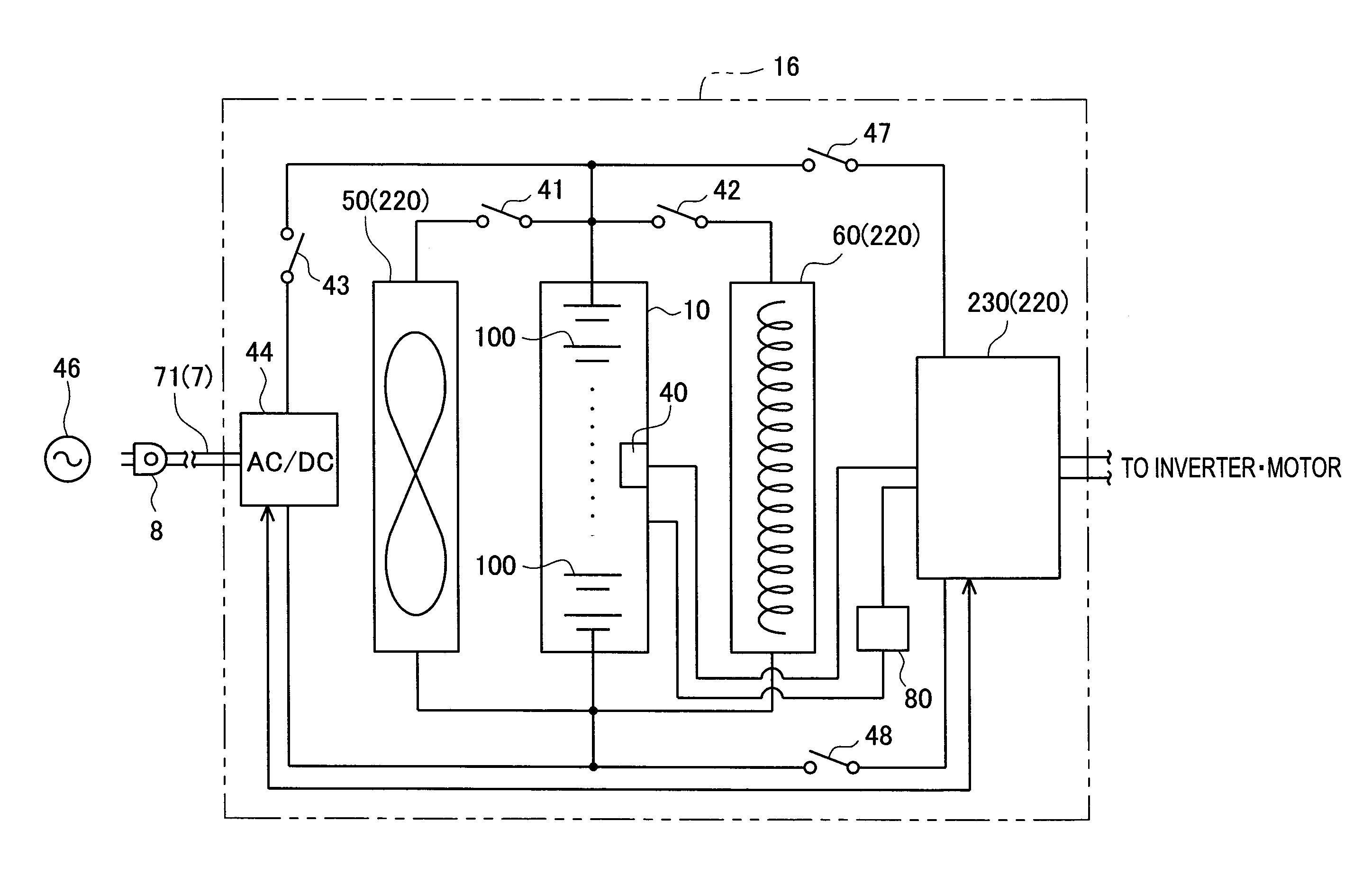
[0127]Hereinafter, a description will be given regarding Example 3 of the present invention, referring to the drawings. FIG. 10 shows a hybrid electric automobile 11 of Example 3. The hybrid electric automobile 11 differs from the hybrid electric automobile 1 of Example 1 in a battery system. There is further provided a power supply plug 8 connected to the battery system. As shown in FIG. 11, a battery system 16 of Example 3 is provided with an assembled battery 10, a temperature control device 220, a conversion device 44 and a voltage detection device 80.

[0128]Of these components, the temperature control device 220 has a microcomputer 230, a cooling device 50 and a heating device 60. And, the voltage detection device 80 detects the voltage of battery (interterminal voltage) of each of the lithium ion secondary batteries 100 constituting the assembled battery 10.

[0129]The conversion device 44, formed by an AC / DC converter, is capable of conversion of the voltage of a commercial powe...


PUM

PropertyMeasurementUnit
temperatureaaaaaaaaaa
temperature Taaaaaaaaaa

Abstract

Disclosed is a battery system wherein safety of a lithium secondary battery can be enhanced by efficiently deactivating (inactivating) lithium metal deposited on a negative electrode of the lithium secondary battery. Also disclosed is an automobile. Specifically disclosed is a battery system comprising a lithium ion secondary battery and a temperature control unit for controlling the temperature of the lithium ion secondary battery. The temperature control unit performs such a control that the temperature T of the lithium ion secondary battery is maintained within the following range: 55° C.<T<65° C., for a predetermined time.

Description

CROSS-REFERENCE TO RELATED APPLICATIONS[0001]This application is a continuation application based upon and claims the benefit of the prior PCT International Patent Application No. PCT / JP2009 / 053167 filed on Feb. 23, 2009, the entire contents of which are incorporated herein by reference.TECHNICAL FIELD[0002]The present invention relates to a battery system equipped with a lithium ion secondary battery, and to an automobile equipped with such a battery system.BACKGROUND ART[0003]Much attention is being paid to lithium ion secondary batteries serving as a power supply for use in portable equipment or serving as a power supply for use in electric automobiles, hybrid electric automobiles and other like vehicles. Incidentally, in a lithium ion secondary battery, the performing of charging (in particular, the performing of high-rate charging), for example, under a low temperature environment may result in the deposition or precipitation of lithium on the surface of a negative electrode. M...

Claims


Application Information

Patent Timeline
Patent Type & Authority Applications(United States)
IPC IPC(8): H02J7/00H01M10/50B60L50/16H01M10/60H01M10/44H01M10/613H01M10/615H01M10/625H01M10/633H01M10/647H01M10/6563H01M10/6571
CPCB60L3/0007Y02T10/705B60L11/187H01M10/052H01M10/486H01M10/5004H01M10/5006H01M10/5016H01M10/5022H01M10/5067H01M10/5083Y02E60/122Y02T10/7005Y02T10/7011B60L3/0046H01M10/625H01M10/615H01M10/633H01M10/6563H01M10/6571H01M10/613B60L58/24B60L58/13B60L58/27B60L58/26Y02E60/10Y02T10/70H01M10/635H01M10/44H01M10/0525
Inventor HAMAGUCHI, HIROSHIWATANABE, MASANORI
Owner TOYOTA JIDOSHA KK
Why Eureka
Try Eureka