Recording device

a recording device and a technology for elongating the movement distance, which is applied in the direction of thin material processing, article separation, printing, etc., can solve the problems of paper riding on the separation slope, unnecessarily cautious, and double feeding of paper, so as to reduce the risk of paper falling off, the effect of efficient rotation of the transmission member

Active Publication Date: 2011-12-01
SEIKO EPSON CORP
View PDF2 Cites 8 Cited by
  • Summary
  • Abstract
  • Description
  • Claims
  • Application Information

AI Technical Summary

Benefits of technology

[0026]According to this configuration, if the vertical line is positioned at the center of the positional range of the rotation angle in the abutting portion, it is possible to more efficiently rotate the transmission member. M...

Problems solved by technology

However, if the user installs the cassette strongly, the papers ride on the separation slope in some cases.
In this case, the plurality of sheets of papers cannot be separated sheet by sheet, which leads to double feeding of paper.
The double feeding of paper leads to a concern over the occurrence of problems such as a paper jam.
Meanwhile, a method of gently installing the cassette is also considered to prevent the paper from riding on the separation slope; however, in this case, the user would become unnecessarily cautious, thus this is not preferable.
Moreover, even when the cassette is gently installed, the papers ride on the separation slop...

Method used


Image

  • Recording device
  • Recording device
  • Recording device

Examples


first embodiment

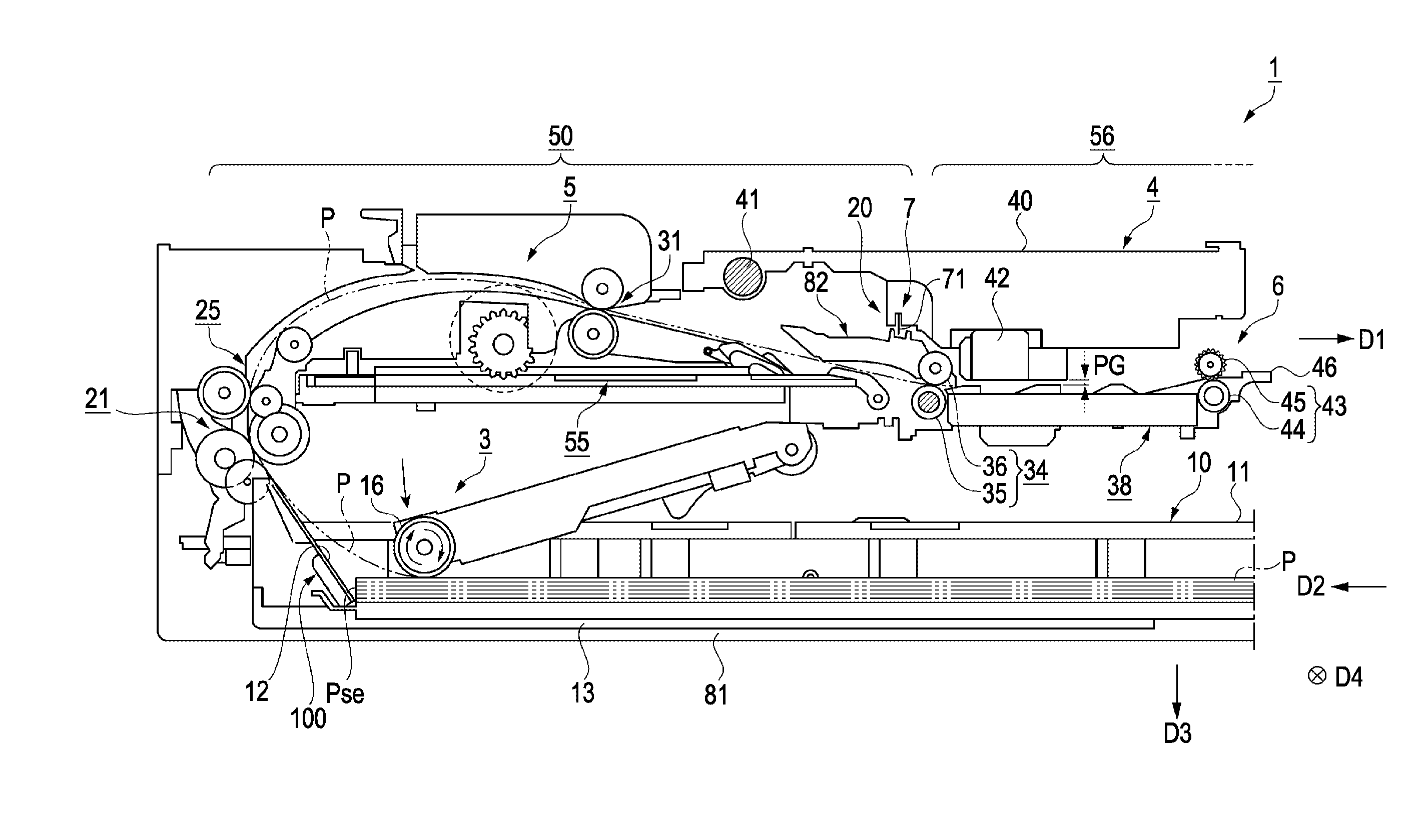
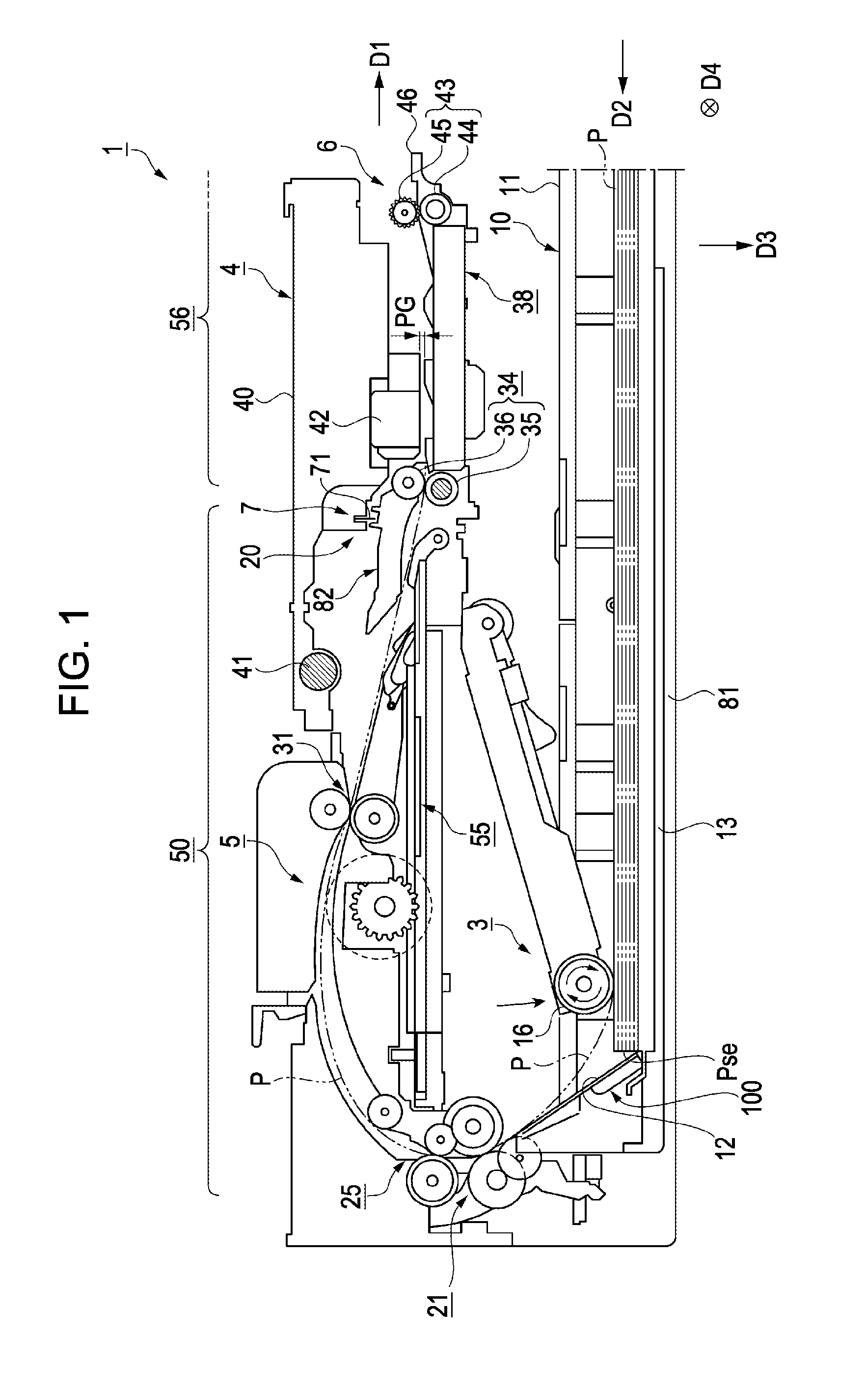
[0043]FIG. 1 is a cross sectional view showing an internal structure of a recording device according to the embodiment. Hereinbelow, the recording device will be described by exemplifying an ink jet printer (hereinafter, referred to as a “printer”).

[0044]As shown in FIG. 1, the recording device 1 in the embodiment is a printer in which a recording head 42 is mounted on the bottom surface of a carriage 40 which crosses a transport direction D1 in a recording execution area 56 and can reciprocate in a width direction D4 that is a vertical direction with respect to the drawing.

[0045]The recording device 1 includes a loading device 10 accommodating a printing paper (hereinafter, referred to as “paper”) P as a plurality of recording media, a feeding device 3 feeding the paper P, a recording portion 4 performing recording on the paper P, a transport device 5 transporting the paper P along a transport path, an encoder device 7 detecting the position of the carriage 40, a discharge device 6...

second embodiment

[0133]In the first embodiment, a state where the lever 150 is used as the transmission member was described; however, in the second embodiment, a state where the cylindrical member is used as the transmission member will be described. FIG. 12 is an exterior perspective view of a cylindrical member 500 as the transmission member in the present embodiment. In other respects, the configuration of the cylindrical member 500 in the loading device of the second embodiment is the same as the configuration of the loading device in the first embodiment.

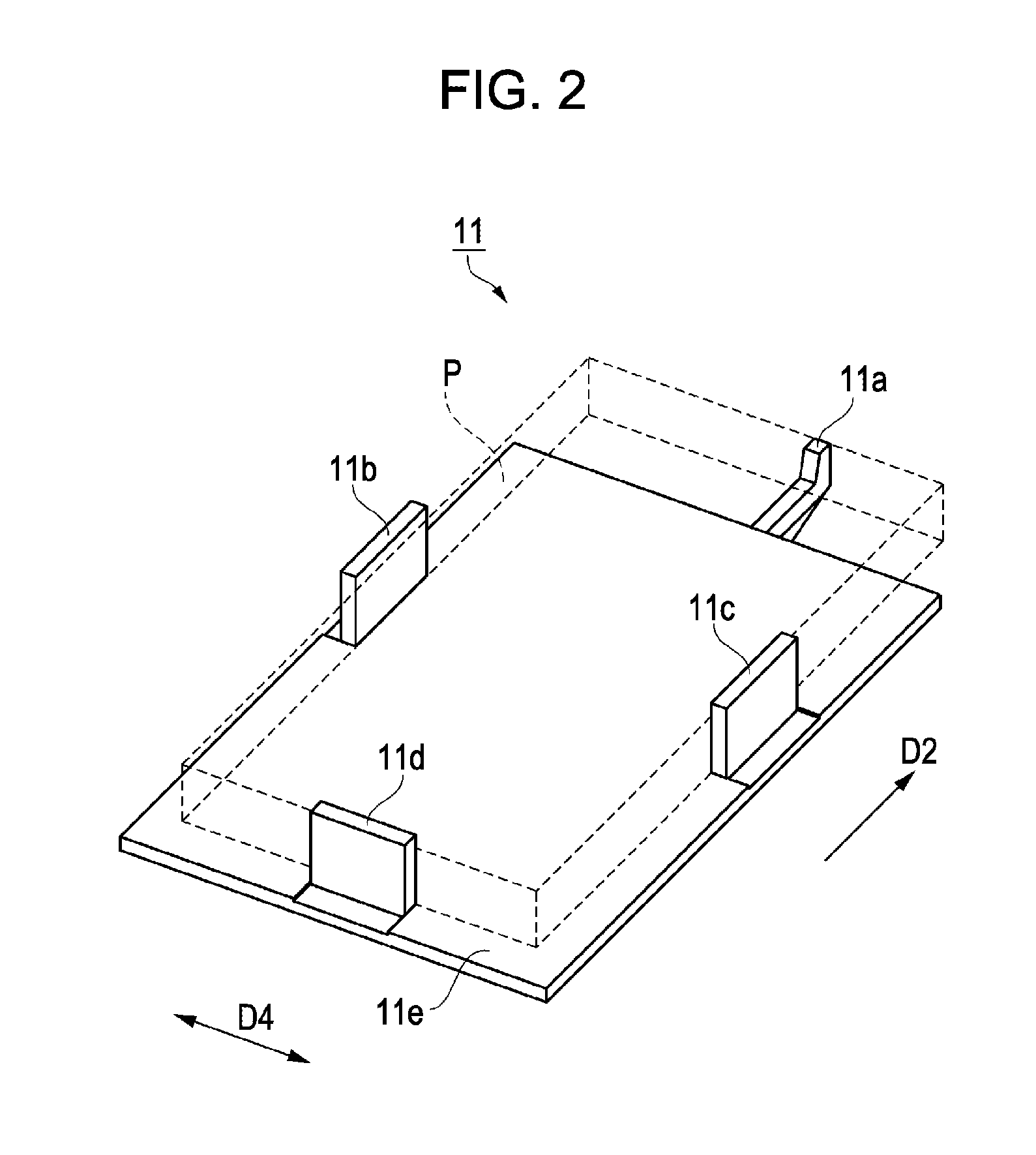
[0134]The cylindrical member 500 includes a first cylindrical member 500a and a second cylindrical member 500b. The first cylindrical member 500a is provided with an abutting portion 500d on which the protruding portion 11a of the cassette 11 abuts. The second cylindrical member 500b is provided with a connection portion 500e as a cylindrical member to which the coil spring 160 is connected.

[0135]The first cylindrical member 500a and the secon...

third embodiment

[0137]In the first embodiment, a state where the slider 130 sliding in the installation direction D2 along the groove portions 120a of the base 120 is used as the first damper portion 200 (see FIGS. 7A and 7B) configuring the damper mechanism portion was described. However, the damper mechanism portion may include a friction portion causing a rod-like member to slide with respect to the cylindrical member, by inserting a rod-like member in the hollow cylindrical member. In other respects, the configuration of the damper mechanism portion in the loading device of the third embodiment is the same as the configuration of the loading device in the first embodiment.

[0138]FIG. 13 is a cross sectional view of a damper mechanism portion in the third embodiment. The damper mechanism portion in FIG. 13 is created by inserting a rod-like member 410 having an outer dimension smaller than the inner dimension of the hollow portion of a cylindrical member 400 into the cylindrical member 400. The o...


PUM


Abstract

A recording device includes a cassette having a protruding portion; a lever as a transmission member in which the distance from a shaft portion to an abutting portion is shorter than the distance from the shaft portion to a connection portion, the lever transmitting a force that the abutting portion receives from the cassette to the connection portion as an acting force by rotating on shaft portion as the axis when the protruding portion of the cassette abuts on the abutting portion; a damper mechanism portion; a separation slope separating the papers; and a stopper as a restriction member restricting the movement of the papers at an upstream side position in the installation direction of the separation slope, and releasing the restriction on the movement of papers by retreating from the position where the stopper restricts the papers when receiving the acting force from the damper mechanism portion.

Description

CROSS REFERENCES TO RELATED APPLICATIONS[0001]The present invention contains subject matter related to Japanese Patent Application No. 2010-123910, filed May 31, 2010, the entire contents of which are incorporated herein by reference.BACKGROUND[0002]1. Technical Field[0003]The present invention relates to a recording device.[0004]2. Related Art[0005]Hitherto, as a kind of recording device, there has been an ink jet printer (hereinafter, referred to as a “printer”). In such a printer, the uppermost paper is taken out of a paper feeding cassette (hereinafter, referred to as a “cassette”) in which a plurality of stacked recording media (for example, printing papers, hereinafter, referred to as “paper”) is disposed, and the paper is fed sheet by sheet to a recording portion (printing portion), whereby printing is performed.[0006]This type of printer is provided with an installation portion for installing a cassette and a paper feeding roller for feeding papers. When the cassette in whic...

Claims


Application Information

Patent Timeline
IPC IPC(8): B41J2/01
CPCB65H1/266B65H3/0684B65H3/56B65H2801/06B65H2403/60B65H2405/31B65H2601/322B65H2402/46
Inventor SHINAGAWA, YUCHINO, HIROKISHIOTA, TAKAYUKI
Owner SEIKO EPSON CORP
Why Eureka
Try Eureka