System and method for measuring flight parameters of a spherical object

Inactive Publication Date: 2011-12-01
KIM JEONG YUL
View PDF1 Cites 19 Cited by
  • Summary
  • Abstract
  • Description
  • Claims
  • Application Information

AI Technical Summary

Benefits of technology

[0010]According to the system and method for measuring flight parameters of a spherical object according to the present invention, it is possible to accurately measure flight parameters including a rotation information of a spherical object with the aid of an inexpensive system unless a device for measuring flight parameters is installed at the floor of a swinging region. The entire manufacture cost of the system can be reduced by implementing the functions of two high speed line scan cameras by using only one inexpensive area camera in such a way to increa

Problems solved by technology

The above conventional golf simulation system is not capable of measuring a rotation information of a golf ball, so a method for estimating a rotation information of a ball by using a motion data (angle, trajectory, etc. of a golf club head) of a golf club is used instead.
In this case, there is a limit in measuring the trajectory of an accurate impact of a golf ball.
When a trigger device is used, the trigger device is provided close to a flight way of a golf ball and a golf club at the time of impact, so interferences between a rigger device, a golf ball and a golf club occur.
The above system, however, is same a currently commercial screen golf system: The prior art 1 cannot accurately measure the rotation information of a golf ball, and it adapts an expensive high speed camera, thu

Method used


Image

  • System and method for measuring flight parameters of a spherical object
  • System and method for measuring flight parameters of a spherical object
  • System and method for measuring flight parameters of a spherical object

Examples


Example

[0033]The system and method for measuring flight parameters of a spherical object according to a preferred embodiment of the present invention will be described in details with reference to the accompanying drawings. In the following descriptions, the scope of the invention is not limited to the disclosed contents, and the present invention might be applied to diverse spherical objects like a baseball ball or the like.

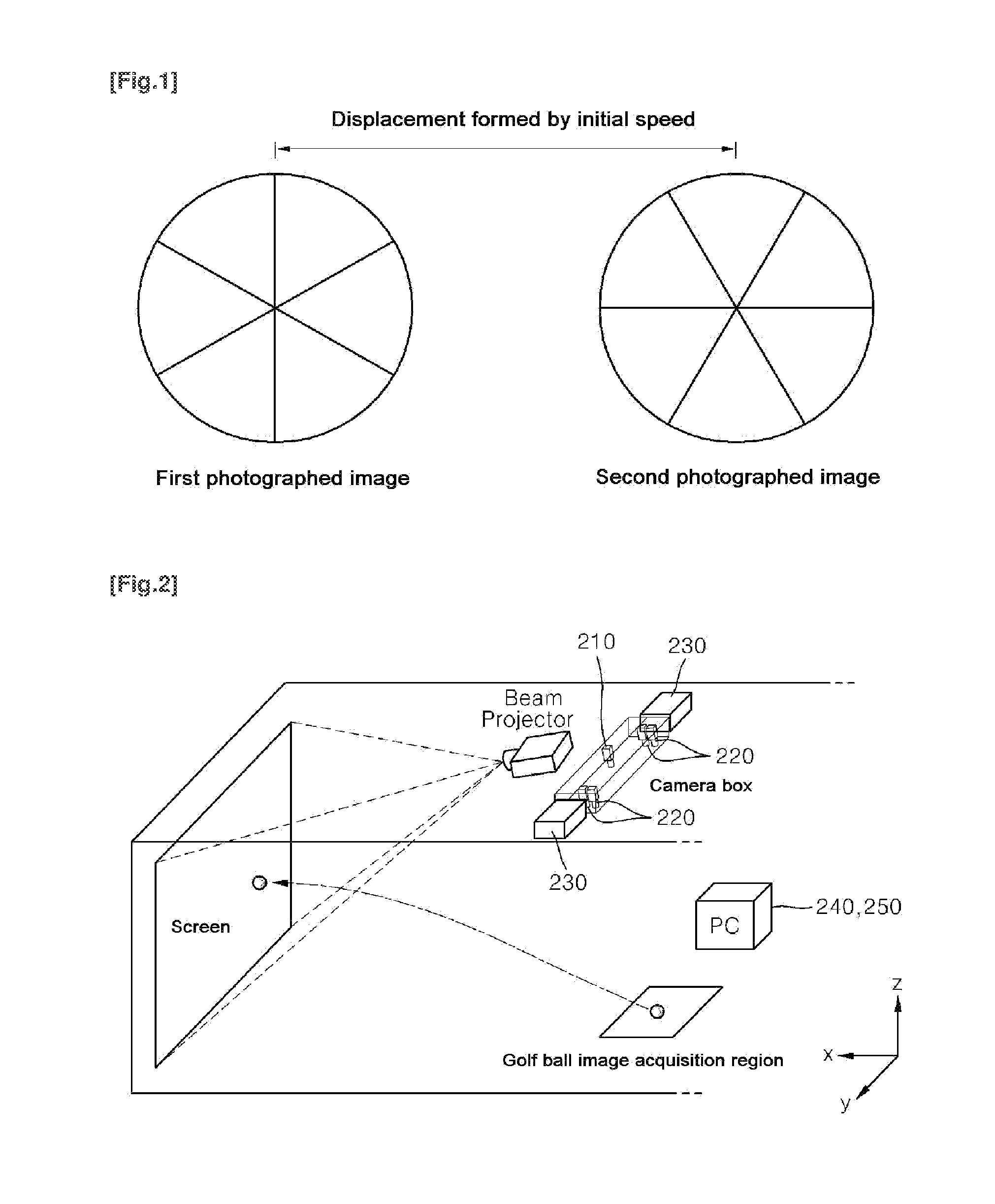
[0034]FIG. 2 is a view illustrating the construction of a system for measuring flight parameters of a spherical object according to a preferred embodiment of the present invention, and FIG. 3 is a block diagram of a construction of a system for measuring flight parameters of a spherical object according to a preferred embodiment of the present invention.

[0035]As shown in FIGS. 2 and 3, the system for measuring flight parameters of a spherical object according to the present invention comprises a trigger signal generation unit 210, a photographing unit 220, a lighting u...


PUM


Abstract

A system and a method for measuring flight parameters of a spherical object are disclosed. A trigger signal-generating unit generates and outputs a first trigger signal upon detection of a spherical object, and generates and outputs a second trigger signal when a reference time interval which is set on the basis of the maximum flight speed and the maximum rotating speed of the spherical object has elapsed from the point in time when the first trigger signal was generated. A photographing unit photographs images in a first image acquiring region having a predetermined region in which the spherical object exists, in accordance with the first trigger signal and the second trigger signal. An image-acquiring unit provides the photographing unit with the first trigger signal and the second trigger signal inputted by the trigger signal generating unit, and converts a plurality of images inputted by the photographing unit in accordance with the first and second trigger signals into digital images, and stores the digital images. A parameter-measuring unit calculates flight parameters including the flight speed, flight angle, rotating speed, and rotational axis of the spherical object from the plurality of digital images.

Description

TECHNICAL FIELD[0001]The present invention relates to a system and method for measuring flight parameters of a spherical object, and in particular to a system and method for measuring fight parameters of a spherical object which make it possible to measure flight parameters including a flight speed, a flight way and a rotation information of a spherical object flight over a space.BACKGROUND ART[0002]A flight way of a spherical object like a golf ball, a baseball ball, etc is determined at a moment that physical force is applied to a ball (namely, impact timing by a golf club or a bat). The information used for determining a flight way of a spherical object is formed of a rotation information of a ball (in other words, a rotation speed and a rotation axis), a flight direction, a speed, etc. There is a golf simulation system which is designed to estimate a flight trajectory of a flight spherical object. Most of the golf simulation systems are directed to generating a lattice shaped se...

Claims


Application Information

Patent Timeline
IPC IPC(8): H04N7/18
CPCA63B24/0021A63B69/3658A63B2024/0031A63B2024/0034A63B2220/30A63B2220/35A63B2243/0025A63B2102/02A63B2102/18A63B2102/32A63B69/36
Inventor KIM, JEONG YUL
Owner KIM JEONG YUL
Why Eureka
Try Eureka