
Camera module and fabrication method thereof

a technology of camera modules and fabrication methods, applied in the field of image sensor technology, can solve the problems of difficult to increase optical performance and reduce the dimensions of camera modules, and the flexibility of the design of the dimension and lens set of high optical performance camera modules

Inactive Publication Date: 2011-12-01
VISERA TECH CO LTD +1
View PDF4 Cites 24 Cited by
  • Summary
  • Abstract
  • Description
  • Claims
  • Application Information

AI Technical Summary

Benefits of technology

[0006]Such a focal distance is varied with the lens set(s) design including the number and shapes of the lenses and the spacer thickness. For high optical performance (e.g. resolution) camera modules, a more complex lens set(s) design may be required, wherein the spacer thickness is reduced, when compared to conventional camera modules. As such, the total thickness of glass spacers used in high optical performance camera modules and required adhesive materials thereof plays an important role in limiting the dimension and lens set design flexibility of a high optical performance camera module. However, since the thinness of the glass spacer thickness is limited to more than 300 μm and requirement for adhesive materials add to the thickness of the glass spacer, it is difficult to increase optical performance and reduce dimensions of camera modules.

Problems solved by technology

As such, the total thickness of glass spacers used in high optical performance camera modules and required adhesive materials thereof plays an important role in limiting the dimension and lens set design flexibility of a high optical performance camera module.
However, since the thinness of the glass spacer thickness is limited to more than 300 μm and requirement for adhesive materials add to the thickness of the glass spacer, it is difficult to increase optical performance and reduce dimensions of camera modules.

Method used


Image

  • Camera module and fabrication method thereof
  • Camera module and fabrication method thereof
  • Camera module and fabrication method thereof

Examples


Embodiment Construction

[0016]The following description is of the best-contemplated mode of carrying out the invention. This description is provided for the purpose of illustrating the general principles of the invention and should not be taken in a limiting sense. The scope of the invention is best determined by reference to the appended claims.

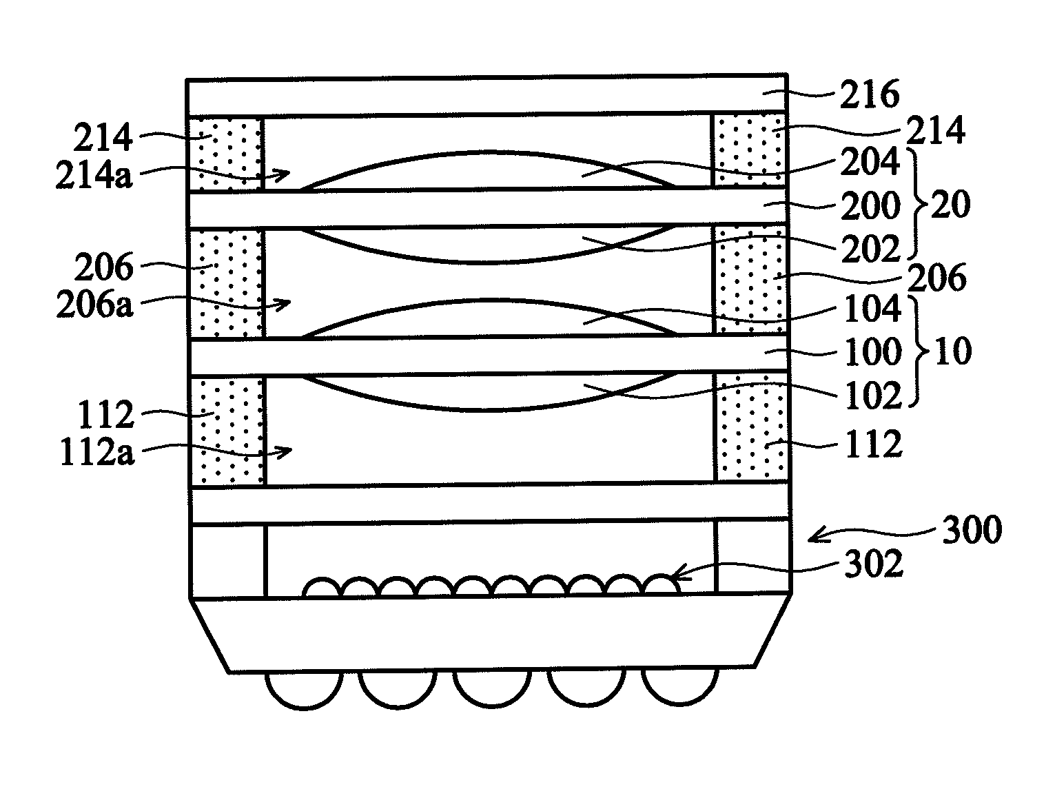
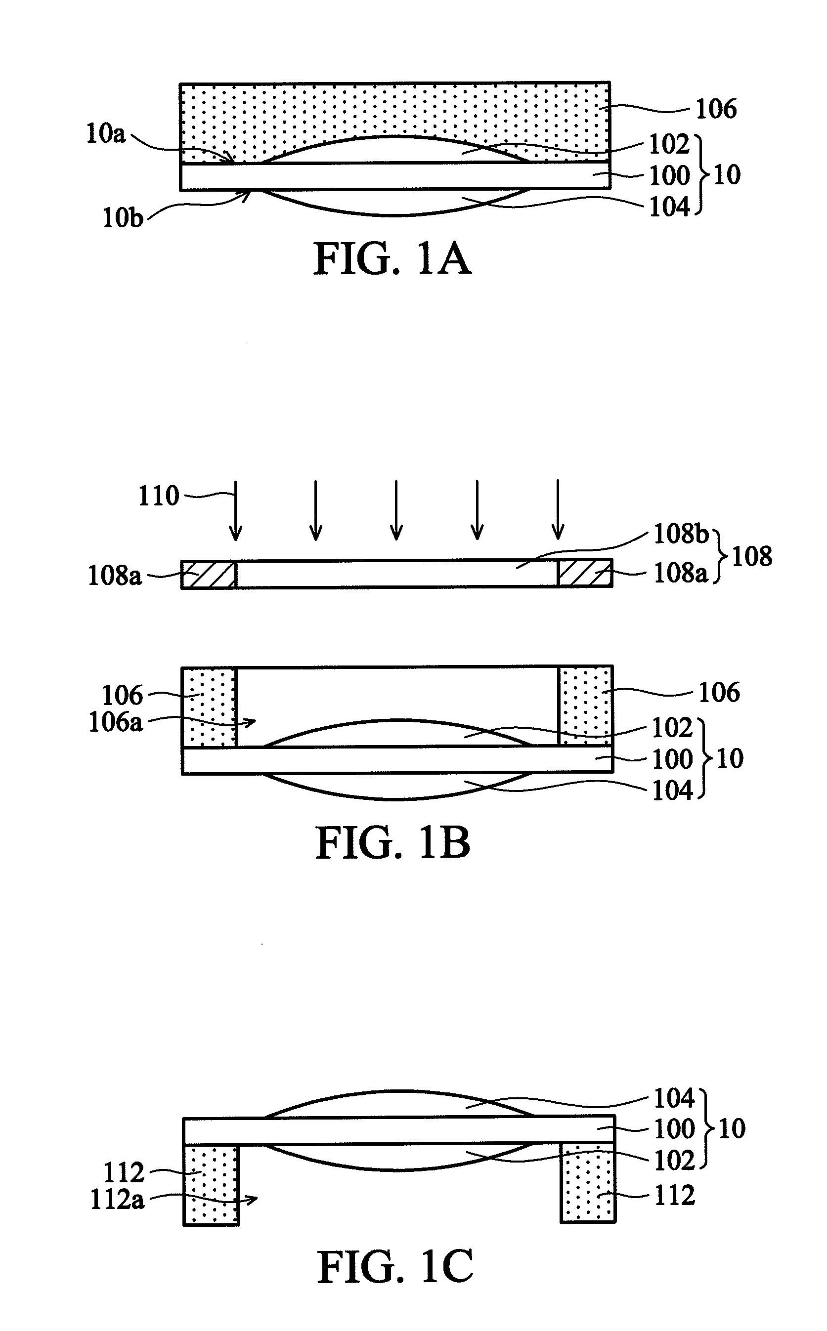
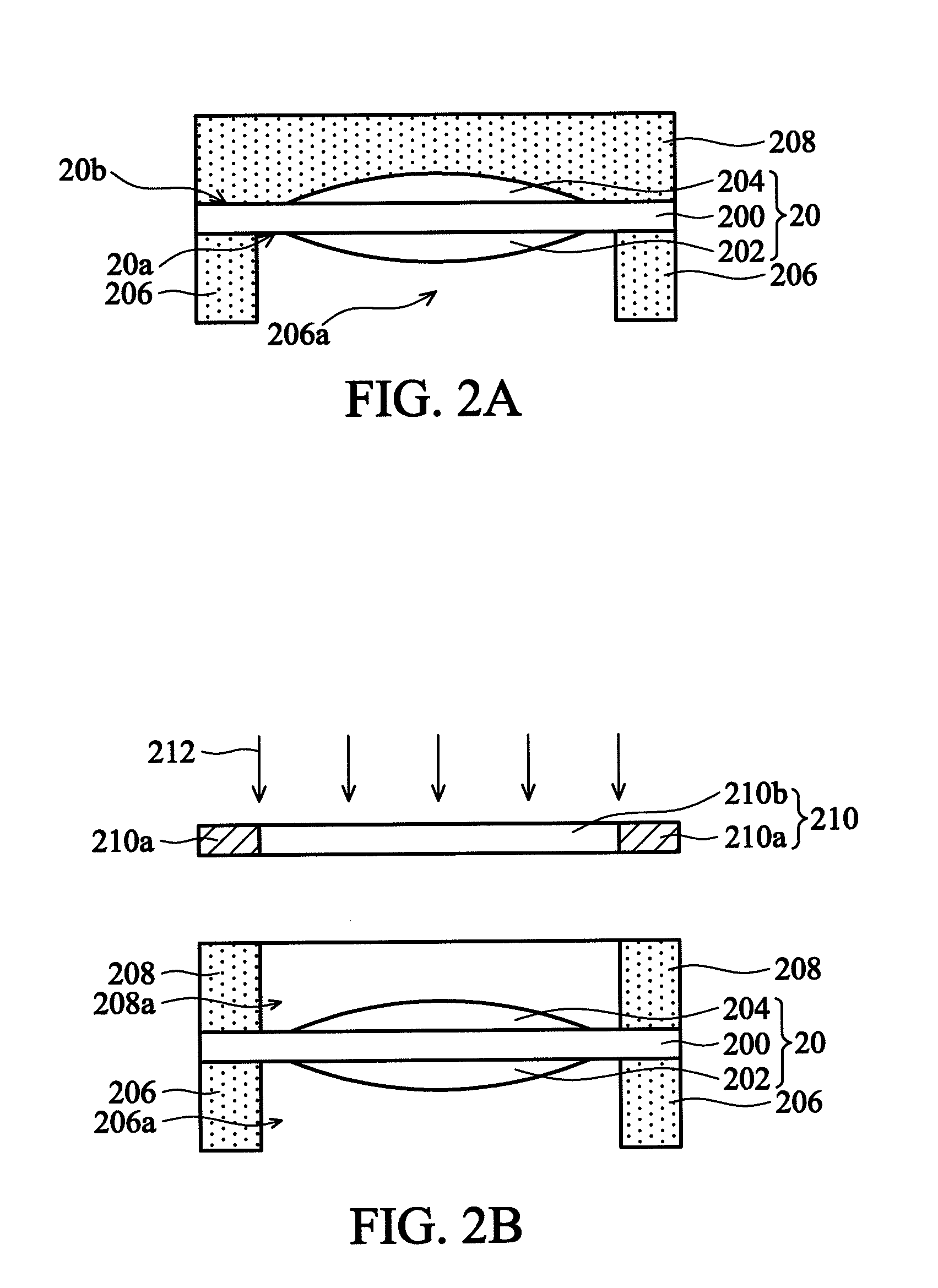
[0017]Referring to FIG. 5A, which illustrates an exemplary embodiment of a camera module according to the invention. In one embodiment, the camera module comprises an imager sensor device 300 comprising a microlens array 302, a lens set 10 is disposed overlying the imager sensor device 300, and a dry film type photoresist spacer 112 interposed between the imager sensor device 300 and the lens set 10. The imager sensor device 300, such as an image pickup or capturing device that is also referred to as a solid-state image sensor (SSIS), may be a CCD or CMOS image sensor.

[0018]The lens set 10 is disposed overlying the imager sensor device 300 through the dry film type...


PUM


Abstract

A camera module is disclosed. The camera module includes an imager sensor device comprising a microlens array. A lens set overlies the imager sensor device. A dry film type photoresist spacer is interposed between the imager sensor device and the lens set, wherein the dry film type photoresist spacer has an opening above the microlens array. A fabrication method of the camera module is also disclosed.

Description

BACKGROUND OF THE INVENTION[0001]1. Field of the Invention[0002]The invention relates to image sensor technology and more particularly to a camera module using photosensitive-type spacers.[0003]2. Description of the Related Art[0004]Charge coupled devices (CCD) and complementary metal oxide semiconductor (CMOS) image sensor devices are widely used in digital imaging applications. Image capture technology is well known to consumers due to the proliferation of devices employing camera modules, including digital cameras, digital video recorders, image capture capable mobile phones, monitors, and other camera-equipped products.[0005]A conventional camera module includes an image sensor device (i.e. an image pickup or capturing device) and one or more lens set(s). The lens sets are disposed on the image sensor device and arranged in a stack so as to map the image of incident light rays onto the image sensor device. Glass spacers are typically disposed between the lens sets and between th...

Claims


Application Information

Patent Timeline
Patent Type & Authority Applications(United States)
IPC IPC(8): H04N5/225H01L31/18H04N25/00
CPCG02B13/0085H01L31/0232H01L27/14618H01L2924/0002H01L31/02327H01L2924/00
Inventor LIN, TZY-YINGCHENG, CHIEH-YUANLIN, HUNG-YEH
Owner VISERA TECH CO LTD
Learn More