

Sectional wind turbine blade
a wind turbine blade and sectional technology, applied in the direction of wind turbines, engine components, wind energy generation, etc., can solve the problems of reducing the strength of joints, reducing the structural strength of blades, and metal bolts needing an even greater cross sectional area
- Summary
- Abstract
- Description
- Claims
- Application Information
AI Technical Summary
Benefits of technology
Problems solved by technology
Method used
Image

Examples
Embodiment Construction
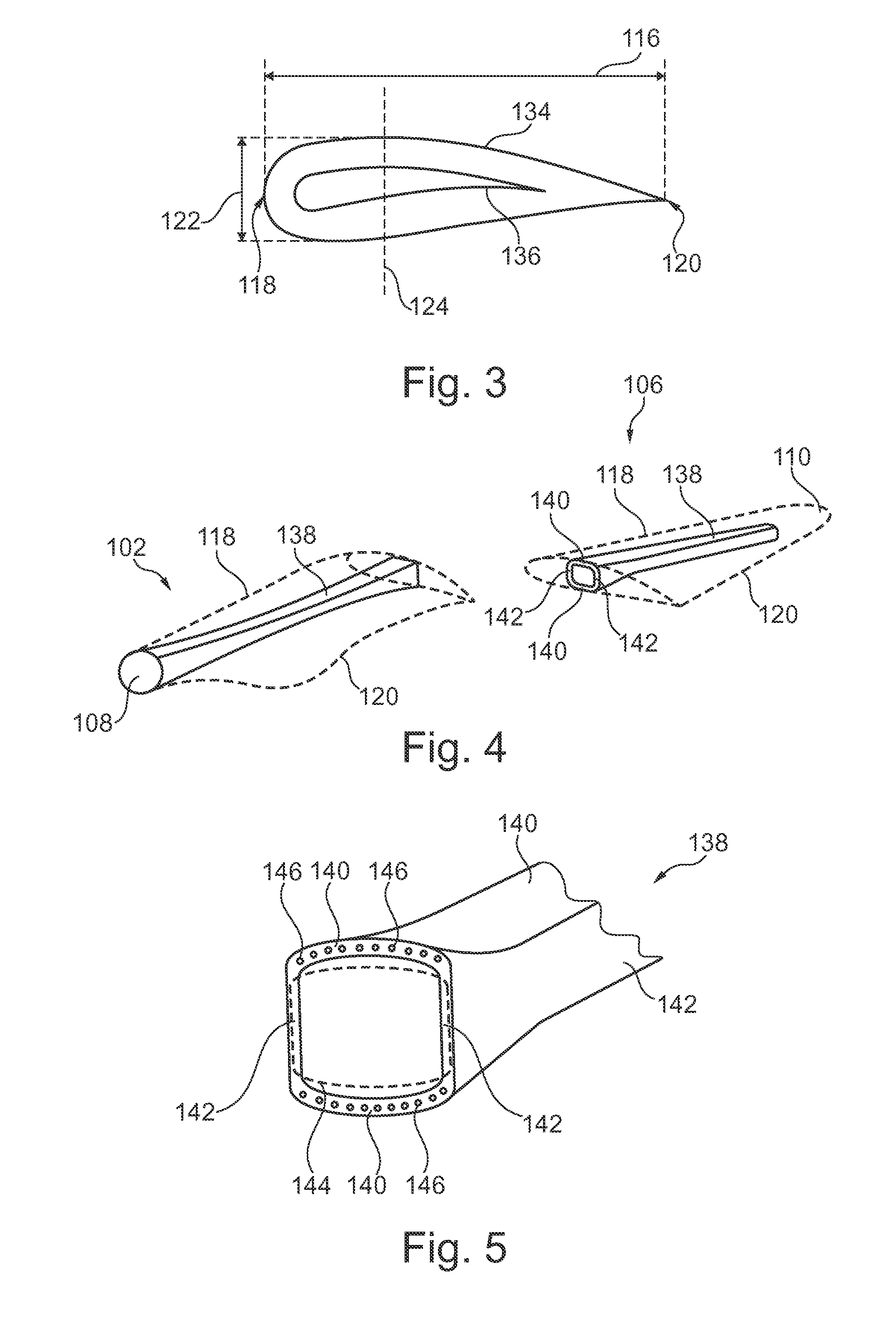
[0010]Compared to conventional blades, it has been found that a slight increase of the width of the chord in the area of the joint compared to neighbouring parts of the blade, while keeping substantially the same chord-to-thickness ratio along the length of the blade, reduces the stress considerably while compromising insignificantly on the aerodynamics of the blade.
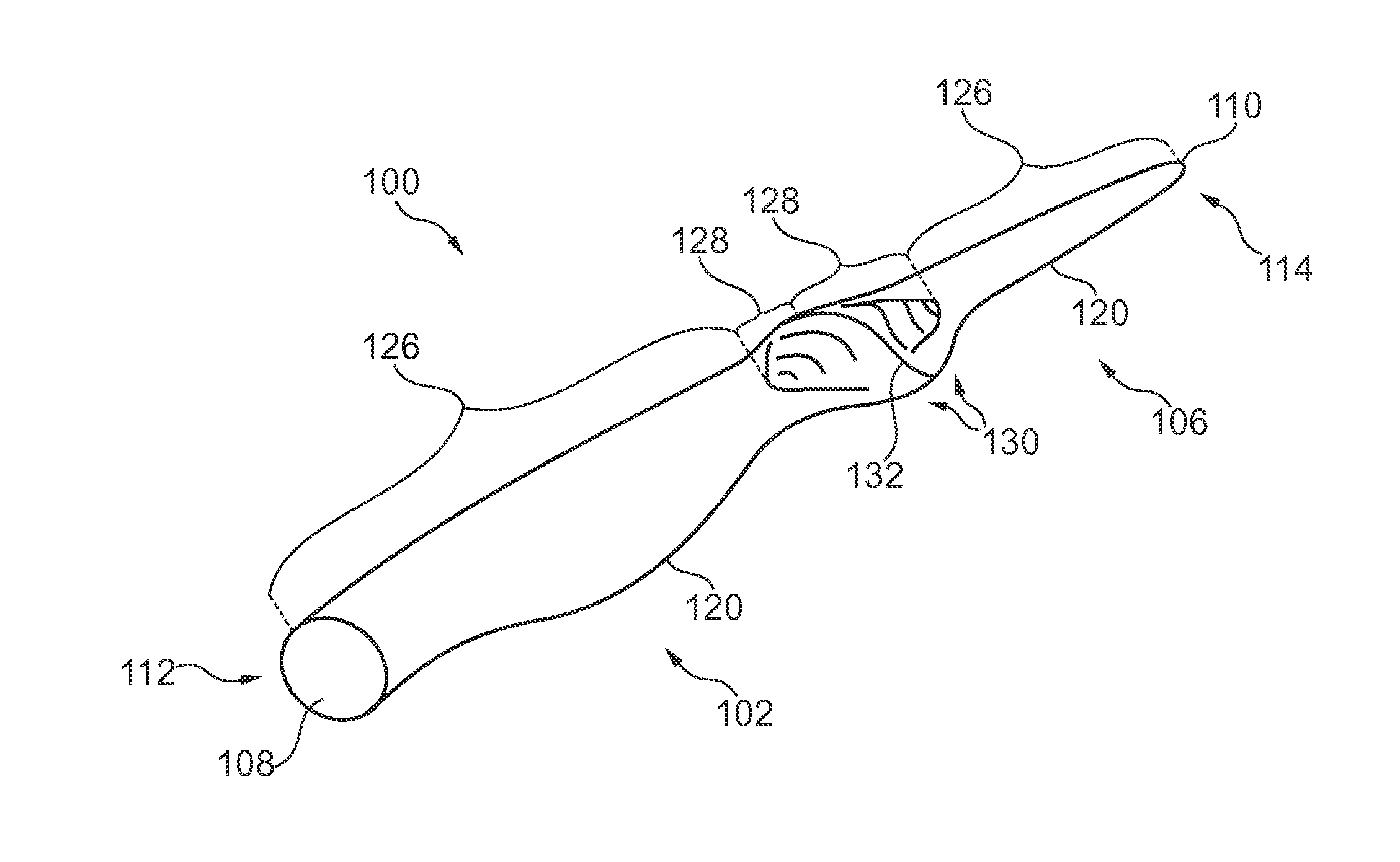
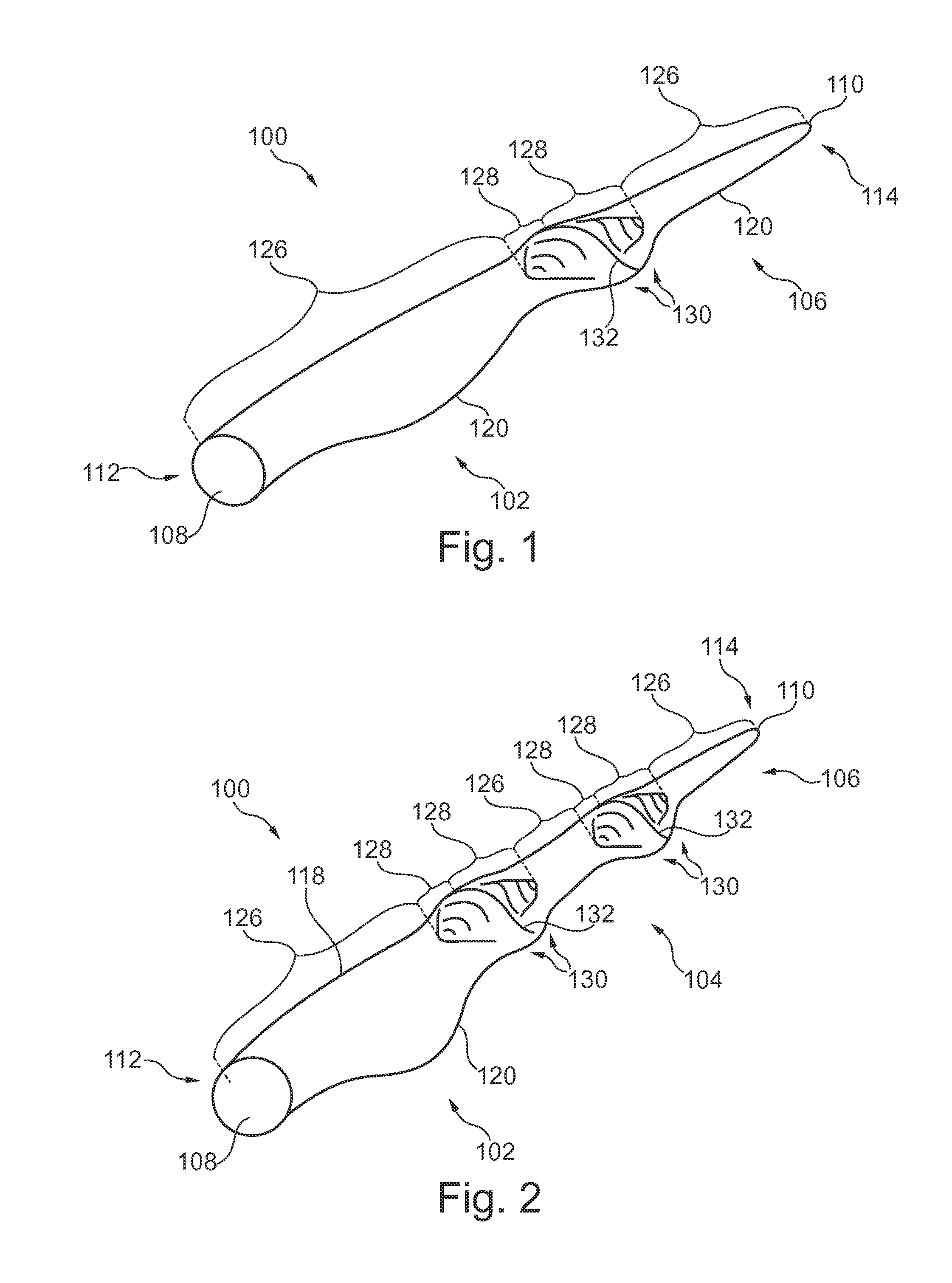
[0011]Thus in a first aspect, the present invention relates to a wind turbine blade defining a chord extending from a leading edge to a trailing edge of the wind turbine blade and a thickness extending in a direction transverse to the chord, the wind turbine blade comprising two or more blade sections each of which defines a non-joint zone and, at one or each of its ends, a joint zone;
wherein the blade sections are connected in pairs such that the joint zones of each pair are connected at a joint, whereby the joint is positioned between two non-joint zones;
wherein at least one of the joints has an increased thickness and...
PUM
 Abstract
Description
Claims
Application Information