
Outboard motor

a technology for outboard motors and motors, which is applied in the direction of motor-driven power plants, vessel construction, marine propulsion, etc., can solve the problems of large pressure difference between the internal pressure of the air intake manifold and the internal pressure of the exhaust passage, and achieve the effect of short distance between the air intake manifold and the communication valve connection, simple configuration and reduced pressure differen

Active Publication Date: 2011-12-01
HONDA MOTOR CO LTD
View PDF7 Cites 3 Cited by
  • Summary
  • Abstract
  • Description
  • Claims
  • Application Information

AI Technical Summary

Benefits of technology

[0005]An object of the present invention is to provide an outboard motor whereby water can be effectively prevented from entering an exhaust passage.
[0008]When reverse rotation is occurring in the engine, the internal pressure of the exhaust passage becomes negative pressure. However, when reverse rotation is occurring in the engine, the communication valve opens, and the air intake manifold and exhaust passage are therefore communicated with each other via the communication passage. The increased-pressure air in the air intake manifold flows into the exhaust passage via the communication valve and the communication passage. As a result, the negative pressure state in the exhaust passage is relieved. Moreover, since the internal pressure of the air intake manifold is increased, this pressure is positive pressure higher than the atmosphere. There is a large pressure difference between the internal pressure of the air intake manifold and the internal pressure of the exhaust passage. The negative pressure state of the exhaust passage can be relieved more quickly by the large pressure difference. Therefore, water can be effectively prevented from flowing into the exhaust passage.
[0010]Furthermore, when reverse rotation is occurring in the engine, the internal pressure of the air intake manifold suddenly increases due to the air flowing back from the air intake port of the engine. As a countermeasure to this, the communication valve is located in the portion where the communication passage and the air intake manifold connect in the present invention. Therefore, the distance in which the air intake manifold and the communication valve connect is extremely short. When the communication valve is open, the air in the air intake manifold flows extremely quickly into the negative pressure communication passage. As a result, excessive pressure increases in the air intake manifold can be quickly avoided.
[0011]Preferably, the communication valve comprises a reed valve or a like check valve which opens when the internal pressure of the air intake manifold is higher than the internal pressure of the exhaust passage. Therefore, the communication valve, which opens only when reverse rotation is occurring in the engine, has a simple configuration as well as high durability. Furthermore, there is no need for electric control for opening the communication valve.
[0012]It is desirable that the communication valve comprise an electromagnetic valve, and the controller control the electromagnetic valve so as to open when a decision has been made that reverse rotation is occurring in the engine. Therefore, when the controller has determined that reverse rotation is occurring in the engine, the electromagnetic valve can be opened either simultaneously or nearly simultaneously with the closing of the throttle valve to a fully closed state. In other words, the electromagnetic valve can be opened even before the pressure difference between the internal pressure of the air intake manifold and the internal pressure of the exhaust passage reaches a specified value. The negative pressure state of the exhaust passage can be relieved even more quickly.

Problems solved by technology

There is a large pressure difference between the internal pressure of the air intake manifold and the internal pressure of the exhaust passage.

Method used


Image

  • Outboard motor
  • Outboard motor
  • Outboard motor

Examples


first embodiment

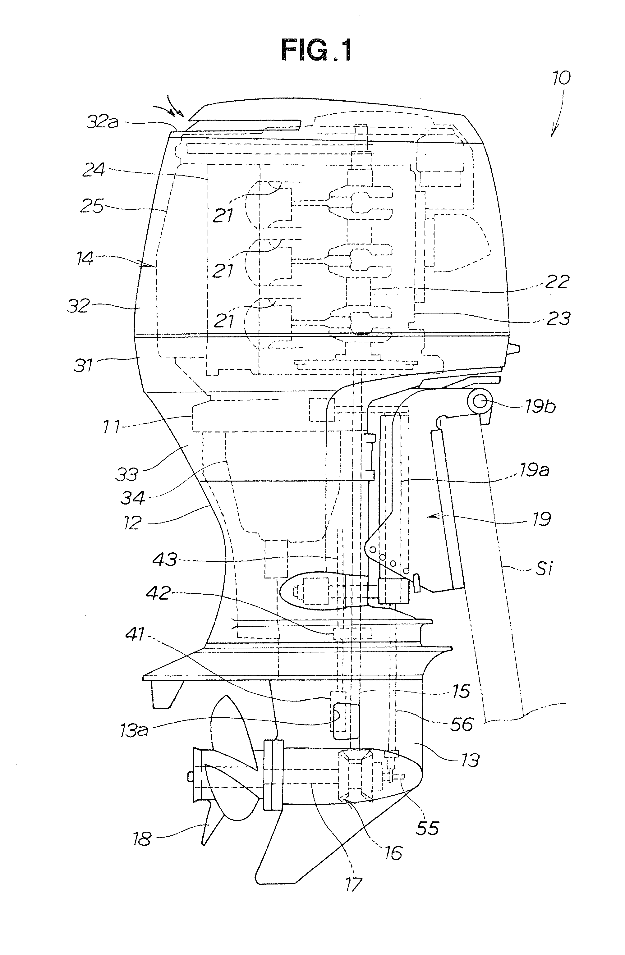
[0026]An outboard motor 10 according to the first embodiment is described hereinbelow based on FIGS. 1 through 8.

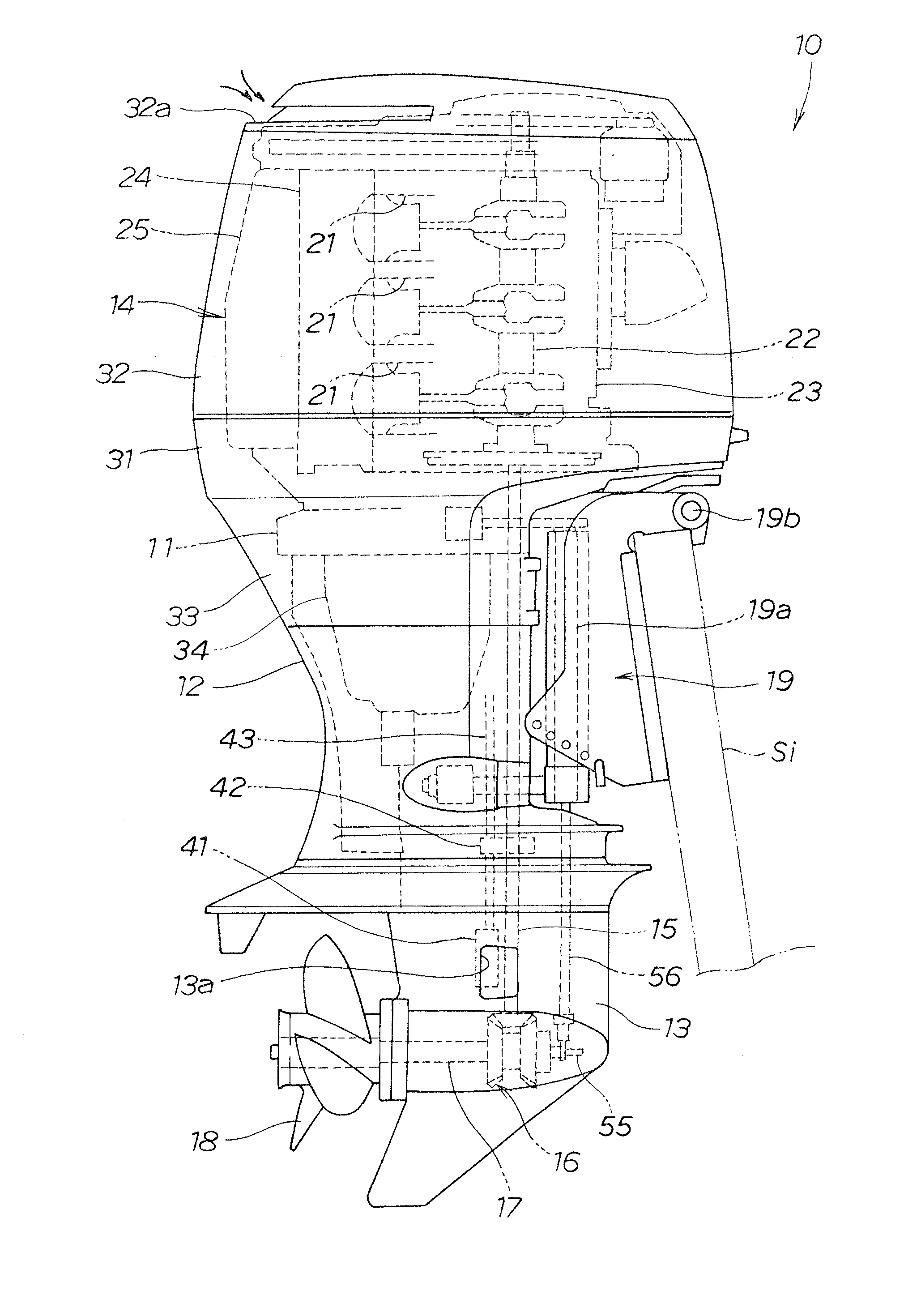
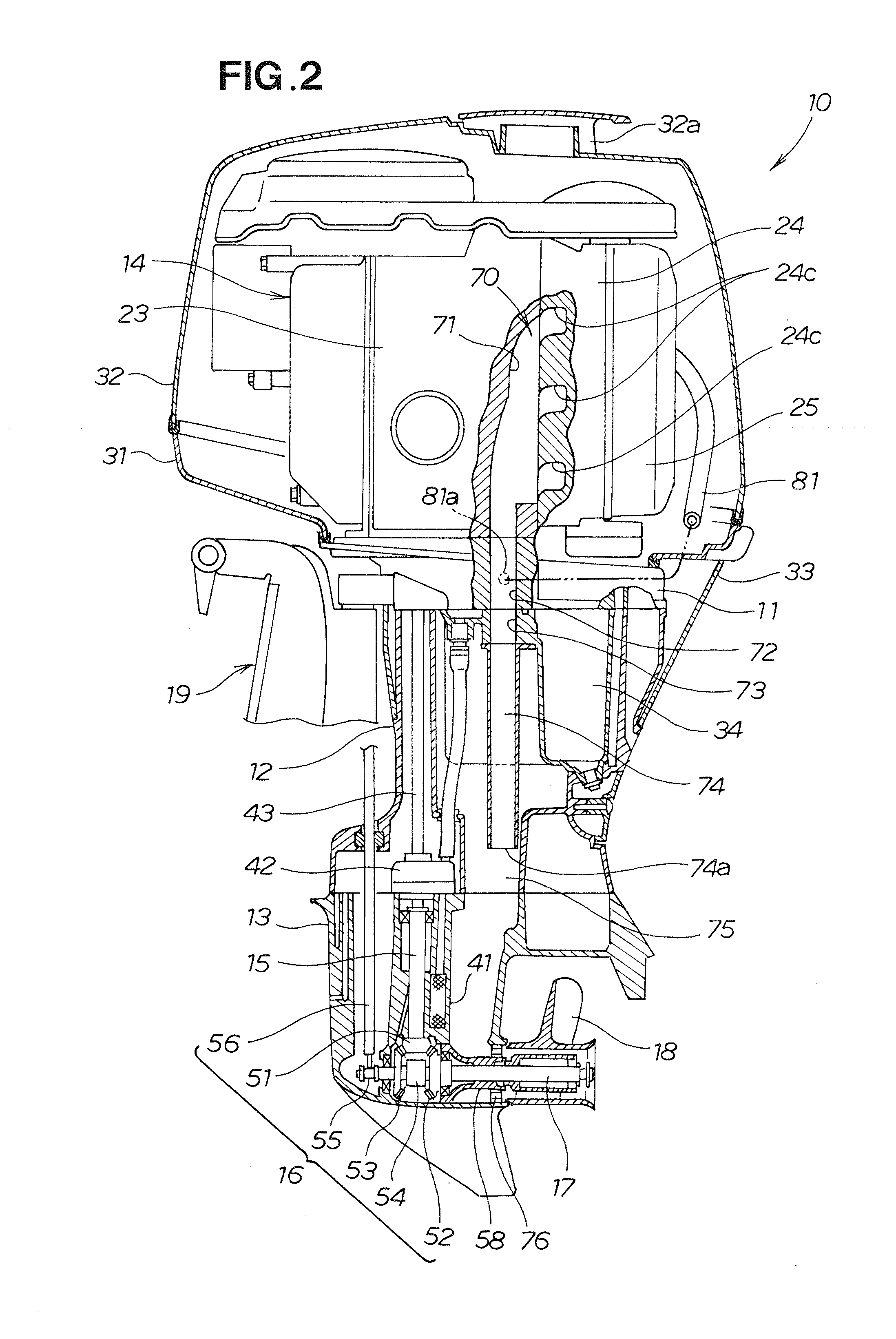
[0027]The outboard motor 10 is composed of a mount case 11, an extension case 12, a gear case 13, an engine 14, a drive shaft 15, a gear mechanism 16, a propeller shaft 17, a propeller 18, and an outboard motor mounting mechanism 19, as shown in FIGS. 1 through 3.

[0028]The outboard motor mounting mechanism 19 is used to affix the outboard motor 10 to the hull Si, and is capable of swinging the outboard motor 10 in a left-right direction about a swivel shaft 19a, as well as raising the outboard motor 10 somewhat in the clockwise direction of FIG. 1 about a tilt shaft 19b.

[0029]The mount case 11 is a so-called engine support case where the engine 14 is mounted on the top surface. The extension case 12 is attached to the bottom part of the mount case 11. The gear case 13 is attached to the bottom part of the extension case 12.

[0030]The engine 14 is a water-cooled vertical m...

second embodiment

[0086]Next, an outboard motor 10A according to the second embodiment is described based on FIGS. 9 through 12. The outboard motor 10A according to the second embodiment is characterized in that the communication valve 82 of the first embodiment shown in FIG. 5 is modified to a communication valve 100 shown in FIG. 9, but the configuration is otherwise identical to the configuration shown in FIGS. 1 through 8 and is not described.

[0087]Specifically, the communication valve 100 of the second embodiment is configured from an electromagnetic valve. When it has been determined that reverse rotation is occurring in the engine 14, the controller 91 of the second embodiment controls the control motor 65 so that the throttle valve 62 is closed to the fully closed state and also controls the communication valve 100 so as to open.

[0088]The electromagnetic valve 100 (the communication valve 100) is located in the connecting portion 63a between the communication passage 81 and the air intake man...


PUM


Abstract

An outboard motor in which exhaust of an engine is emitted into water via an exhaust passage. The outboard motor comprises a throttle valve connected to an air intake port of the engine via an air intake manifold, a control motor for driving the throttle valve to open and close, and a controller for controlling the control motor. The controller controls the control motor such that the throttle valve fully closes when a determination is made that reverse rotation is occurring in the engine. The exhaust passage is communicated with the air intake manifold via a communication passage. A communication valve which opens only when reverse rotation is occurring in the engine is located at a portion where the communication passage and the air intake manifold connect.

Description

FIELD OF THE INVENTION[0001]The present invention relates to an improvement in an outboard motor in which negative pressure occurring in an exhaust system is relieved by causing the engine to rotate in reverse.BACKGROUND OF THE INVENTION[0002]An outboard motor mounted in the rear part of a hull creates thrust in the hull by causing a propeller to rotate using the motive power of an engine. Exhaust created by the driving of the engine is emitted into the water via an exhaust passage. The outboard motor further comprises a shift mechanism for shifting the traveling direction of the hull between forward and reverse. By operating the shift mechanism and shifting the engaged state of the clutch, the rotating direction of the propeller can be reversed. In other words, the clutch shifts the rotating direction of the propeller to forward or reverse in relation to the rotating direction of the engine.[0003]At a point in time when the shift mechanism switches from forward to reverse while the...

Claims


Application Information

Patent Timeline
Patent Type & Authority Applications(United States)
IPC IPC(8): B63H21/21B63H21/32B63H21/14
CPCF02M35/168B63H21/32
Inventor YAMAZAKI, AKIHIKOTAKADA, HIDEAKI
Owner HONDA MOTOR CO LTD
Learn More