Vehicle engine controller

a technology for engine controllers and vehicles, applied in the direction of electric control, machines/engines, instruments, etc., can solve the problems of engine output suppression, vehicle cannot be started, and the safety at the time of both accelerator pedals and brake pedals being pressed cannot be secured sufficiently

Active Publication Date: 2011-12-01
DENSO CORP
View PDF13 Cites 13 Cited by
  • Summary
  • Abstract
  • Description
  • Claims
  • Application Information

AI Technical Summary

Benefits of technology

[0011]It is an object of the present invention to provide a vehicle engine controller cap

Problems solved by technology

Therefore, there is a possibility that the engine output is suppressed and the vehicle cannot be started although a driver intends to accelerate the vehicle.
T

Method used


Image

  • Vehicle engine controller
  • Vehicle engine controller
  • Vehicle engine controller

Examples


first embodiment

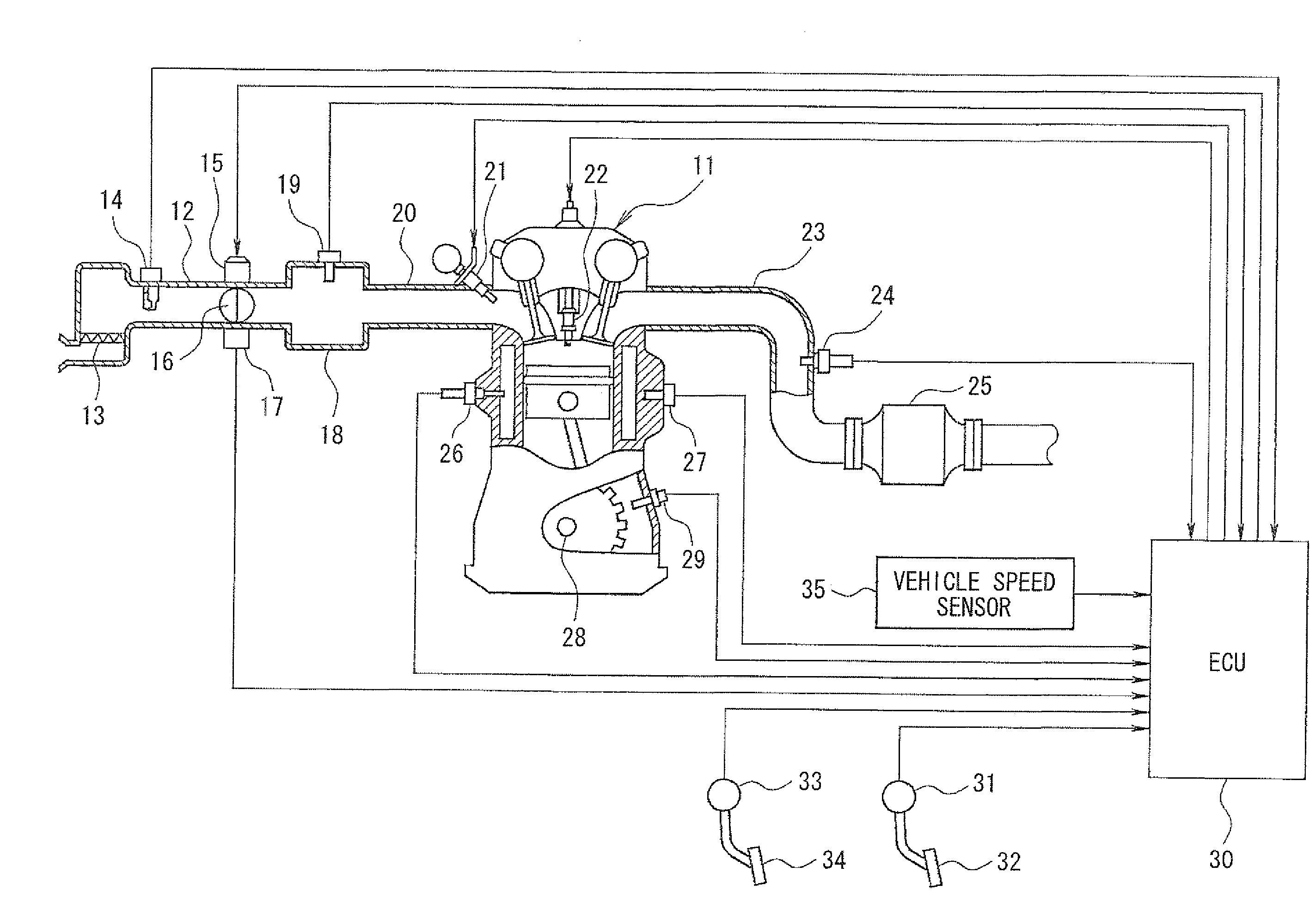
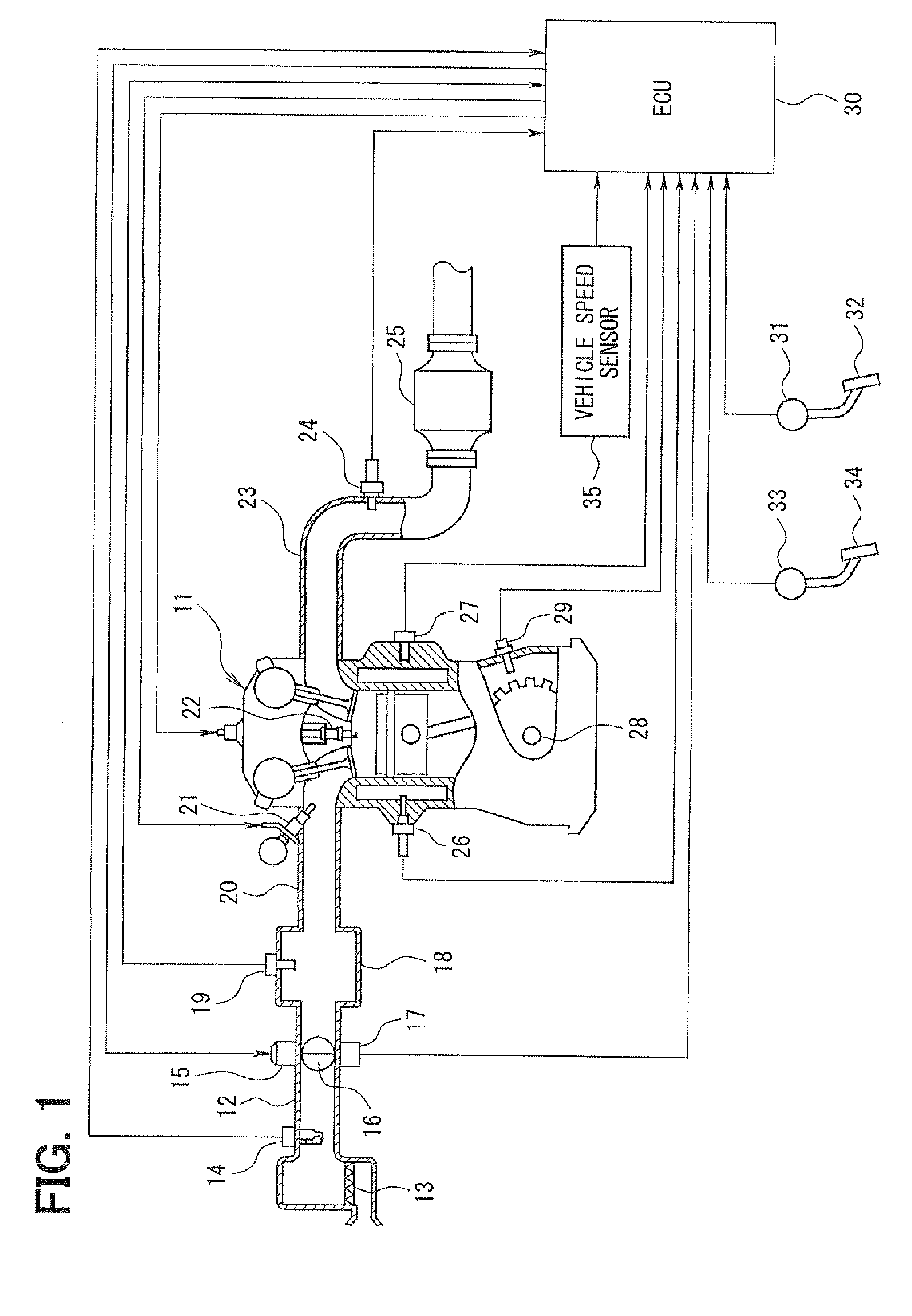
[0039]First, a first embodiment of the present invention will be explained with reference to FIGS. 1 to 3. First, a schematic construction of an entire engine control system will be explained with reference to FIG. 1. An air cleaner 13 is provided in the most upstream portion of an intake pipe 12 of an engine 11 (internal combustion engine). An airflow meter 14 for sensing an intake air quantity is provided downstream of the air cleaner 13. A throttle valve 16, whose opening degree is regulated by a motor 15, and a throttle position sensor 17 for sensing an opening degree of the throttle valve 16 (i.e., throttle position) are provided downstream of the airflow meter 14.

[0040]A surge tank 18 is provided downstream of the throttle valve 16, and an intake pipe pressure sensor 19 for sensing intake pipe pressure is provided in the surge tank 18. An intake manifold 20 for introducing the air into each cylinder of the engine 11 is provided to the surge tank 18. An injector 21 is attached ...

second embodiment

[0097]Next, a second embodiment of the present invention will be explained with reference to FIGS. 4 to 6. In the following description, differences from the first embodiment will be explained mainly.

[0098]In the second embodiment, the ECU 30 executes respective routines shown in FIGS. 4 to 6 (explained later) for the accelerator position output control. Thus, the accelerator position output control simplified as compared to the accelerator position output control of the first embodiment is performed. Next, processing contents of the respective routines shown in FIGS. 4 to 6 for the accelerator position output control will be explained.

[0099](Accelerator Position Output Control Routine)

[0100]The accelerator position output control routine shown in FIG. 4 is executed repeatedly in a predetermined cycle while a power supply of the ECU 30 is ON. If the routine of FIG. 4 is started, first in S101, it is determined whether the vehicle speed is equal to or higher than a predetermined valu...


PUM


Abstract

If it is determined that a brake pedal is pressed while an accelerator pedal is pressed, accelerator position limit control for bringing an accelerator position for engine control to a limit value corresponding to vehicle speed is performed, thereby securing safety at the time when both of the accelerator pedal and the brake pedal are pressed. If it is determined that the accelerator pedal is pressed after the brake pedal is pressed, the accelerator position limit control is prohibited, thereby responding to driver's intention to accelerate. If it is determined that the pressing of the brake pedal is cancelled during execution of the accelerator position limit control, accelerator position recovery control for returning the accelerator position for the engine control to an actual accelerator position is performed, thereby recovering normal running corresponding to the driver's intention to accelerate.

Description

CROSS REFERENCE TO RELATED APPLICATION[0001]This application is based on and incorporates herein by reference Japanese Patent Application No. 2010-122147 filed on May 27, 2010.BACKGROUND OF THE INVENTION[0002]1. Field of the Invention[0003]The present invention relates to a vehicle engine controller that controls an engine based on an accelerator position sensed with an accelerator sensor.[0004]2. Description of Related Art[0005]There is a vehicle mounted with a recent electronically-controlled engine (internal combustion engine) having an accelerator sensor for sensing a pressed amount of an accelerator pedal (i.e., accelerator position). The vehicle controls a throttle position (or intake air quantity) and the like based on the accelerator position sensed with the accelerator sensor, thereby controlling an output of the engine.[0006]For example, Patent document 1 (JP-A-2005-291930) describes a technology that aims to improve safety of such a vehicle. The technology of Patent docum...

Claims


Application Information

Patent Timeline
IPC IPC(8): B60W10/06B60W30/18F02D29/02F02D45/00
CPCF02D2011/102F02D11/105F02D2200/702F02D2200/501F02D2250/26F02D2200/602Y10T477/8936F02D2250/28
Inventor NODERA, MASATOMURAKAMI, YOSHIFUMI
Owner DENSO CORP
Why Eureka
Try Eureka