Cooking equipment

Inactive Publication Date: 2011-12-08
LIU XINYU
View PDF9 Cites 18 Cited by
  • Summary
  • Abstract
  • Description
  • Claims
  • Application Information

AI Technical Summary

Benefits of technology

[0018]With the cooking equipment of the present invention all cooking steps, including feeding material, stirring material, and taking out material, can be realized automatically. Furthermore, the pot has two freedoms of motion, which can make the pot rotate and turn

Problems solved by technology

At present, Chinese dishes are still prepared manually by chef, which is not only detrimental to the health of the cooker, but also can not warrant the quality of Chi

Method used


Image

  • Cooking equipment
  • Cooking equipment
  • Cooking equipment

Examples


Embodiment Construction

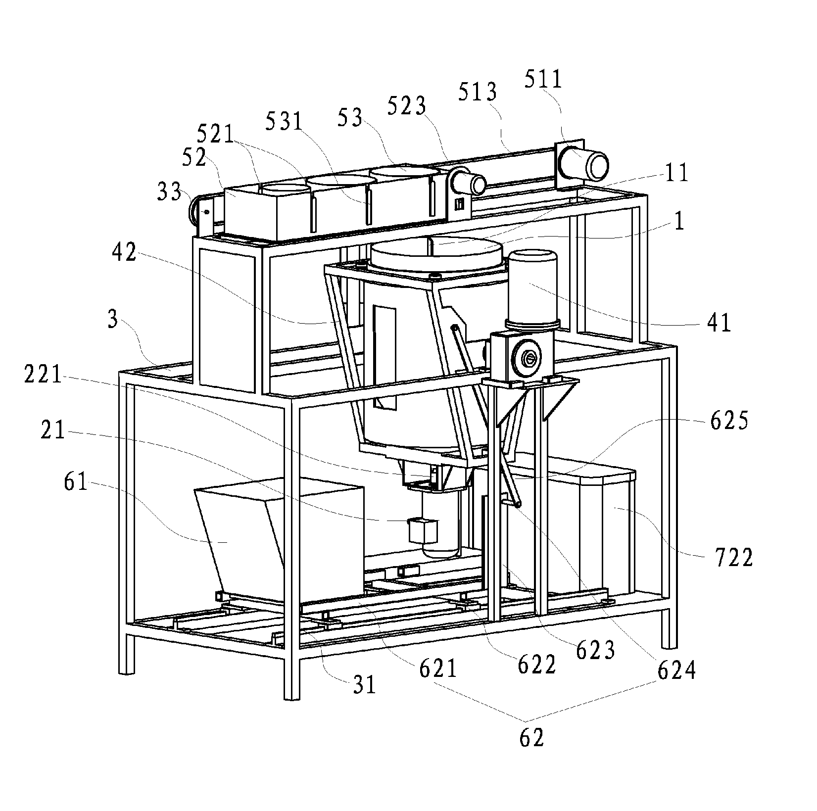
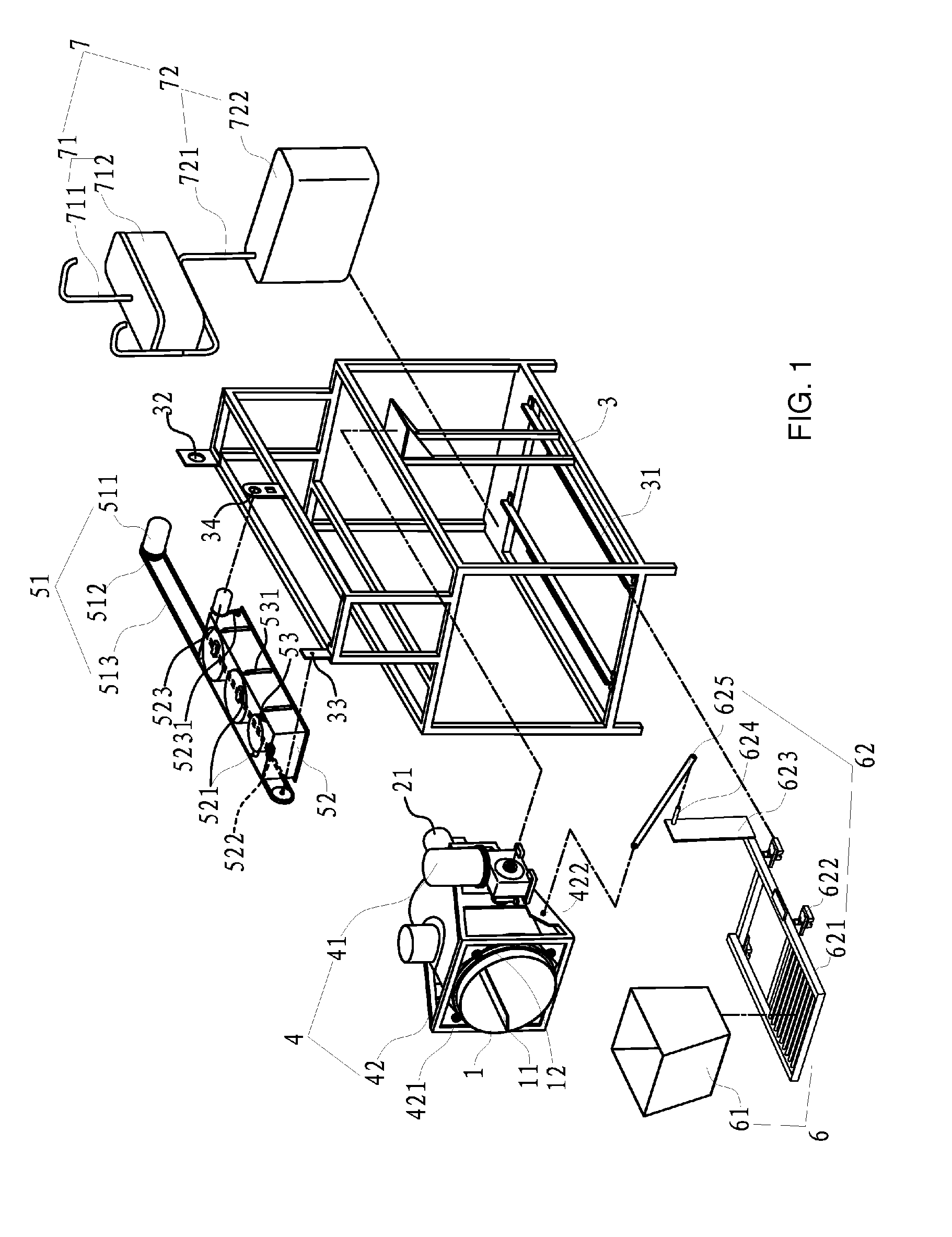
[0028]Please refer to FIG. 1, an explosive schematic view of a cooking equipment in an embodiment according to the present invention. The cooking equipment disclosed in FIG. 1 comprises a pot 1, a rotation mechanism 2, a body bracket 3, a turning-over mechanism 4, a feeding mechanism 5, a taking-out mechanism 6 and a supplying mechanism 7.

[0029]The pot 1 is in shape of a barrel, whose cross section is in shape of a circle. It has an opening at its end. A stirring mechanism is installed inside the pot 1. The stirring mechanism is two baffles 11 inside the pot 1. The baffles 11 are perpendicular to the tangent of the internal surface of the pot 1, and there is arc transitions between the baffles 11 and the internal surface. The baffles 11 are so conFigured that when the baffles 11 rotate together with the pot 1 they will bring the material inside the pot 1 to higher positions and then throw the material to lower positions to stir the material evenly.

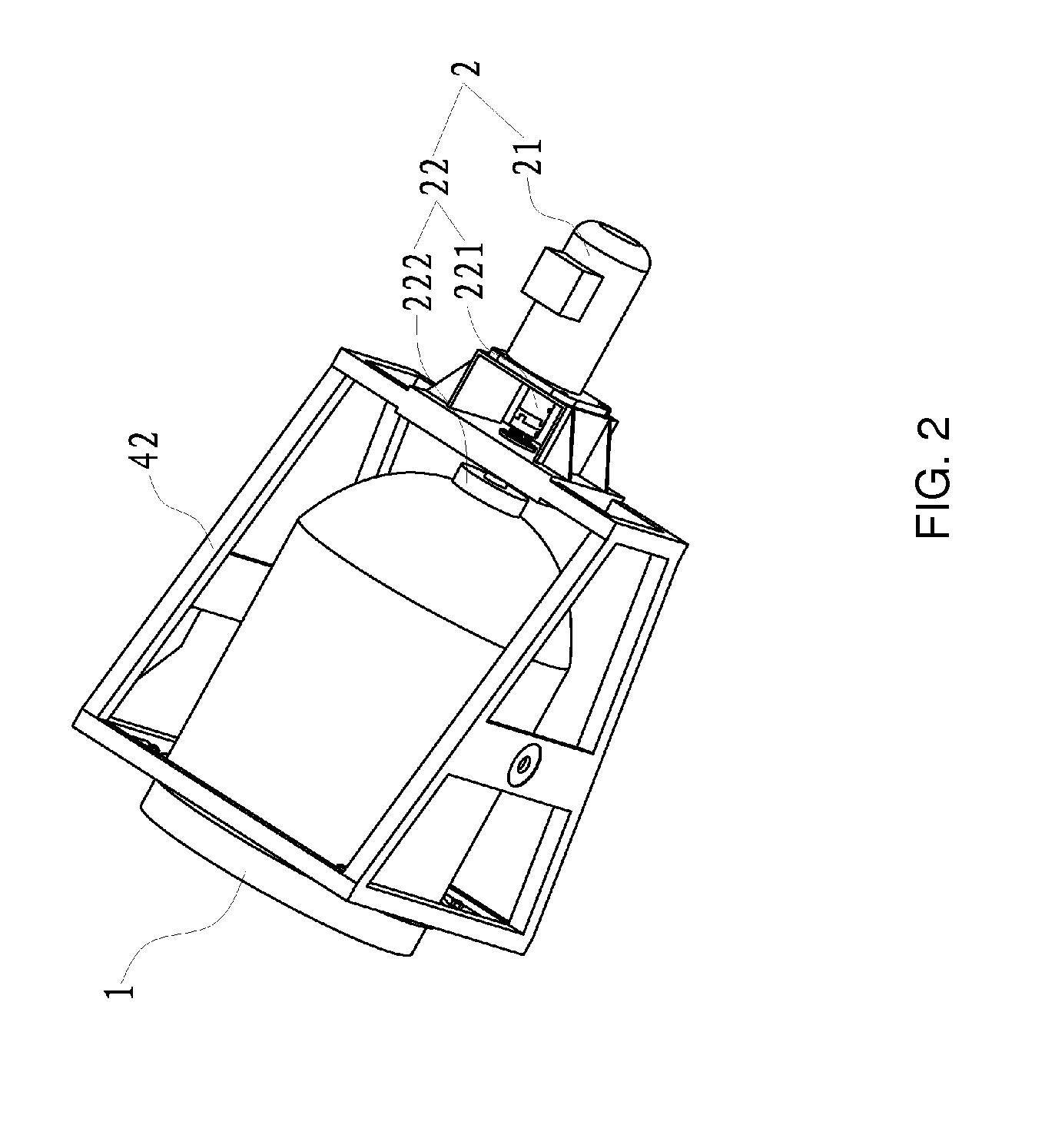
[0030]Refer now to FIG. 2, in which...


PUM


Abstract

The present invention provides a cooking equipment comprising a pot, a body bracket, a rotation mechanism and a turning-over mechanism in which the pot is in shape of a barrel, a hemisphere or the like with an opening at its end, the rotation mechanism is connected to the pot to drive the pot to rotate around a rotation axis of the pot, the turning-over mechanism is connected to the pot to drive the pot to turn around a turning-over axis together with the body bracket, and when the cooking equipment is in its operating state, the angle between the rotation axis of the pot and horizontal plane is in the range of 0° to 90°.

Description

TECHNICAL FIELD OF THE PRESENT INVENTION[0001]The present invention relates to kitchen utensils in the cooking filed, and more specifically to a cooking equipment.BACKGROUND OF THE PRESENT INVENTION[0002]At present, Chinese dishes are still prepared manually by chef, which is not only detrimental to the health of the cooker, but also can not warrant the quality of Chinese dishes themselves.[0003]Chinese patent application 02117497.0 disclosed an automatic pot used for frying dish and stewing soup. Computer controlling was employed in this application to make complex manual operations become automated operations. It possessed a series of functions such as feeding material, stir-frying, boiling, frying, adding seasoning ingredients, taking out finished dishes, pouring soup, washing pot, etc. Although this kind of automatic pot could rotate, it could rotate only along one direction, and the rotation could not be used to stir material. In addition, the direction of rotation would make t...

Claims


Application Information

Patent Timeline
IPC IPC(8): A47J27/00
CPCA47J27/14A47J27/002
Inventor LI, LINGYAN, PING
Owner LIU XINYU
Why Eureka
Try Eureka