
Electric motor

a technology of electric motors and magnets, applied in the direction of dynamo-electric machines, electrical apparatus, magnetic circuits, etc., can solve the problems of brittle ceramic magnets and easy breakage under mechanical stress, and achieve the effect of improving the resistance to axial shifting and rattling

Inactive Publication Date: 2011-12-08
EBM PAPST ST GEORGEN & -
View PDF2 Cites 11 Cited by
  • Summary
  • Abstract
  • Description
  • Claims
  • Application Information

AI Technical Summary

Benefits of technology

[0003]It is therefore an object of the invention to make available a novel electric motor structure with improved resistance to rattling and axial shifting.
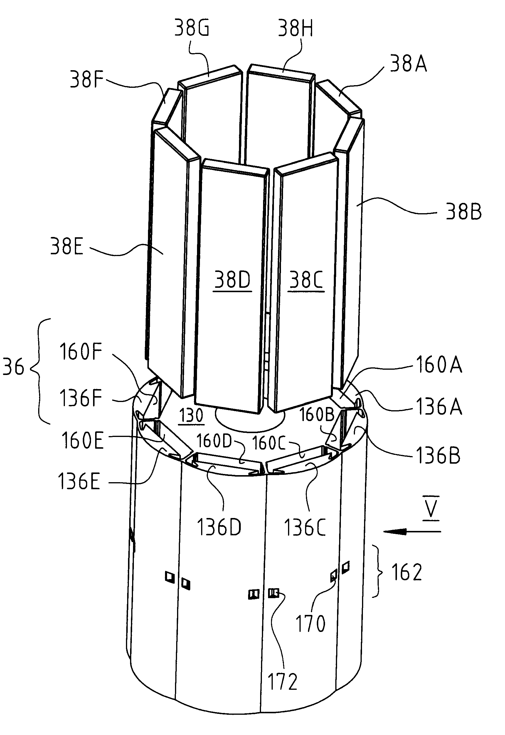
[0004]According to the invention, this is achieved by forming the rotor with an annular central yoke connecting to a plurality of pole shoes along the periphery of the rotor and defining a magnet-receiving recess or pocket between each pole shoe and the central yoke. Spaced circumferentially between adjacent magnets are regions of reduced magnetic conductivity, which include relatively thin metallic holding segments which connect adjacent pole shoes to each other, and to the central yoke. During manufacturing, tools are applied radially inward toward the rotor central axis, to upset or crimp the holding segments and thereby form spring elements, to hold the magnets in stable positions and resist any tendency of the magnets to rattle or axially shift during motor operation. This yields an electric motor in which it is possible to use, in the rotor, ceramic magnets whose angular extent is not much narrower than a pole pitch of the rotor, and in which one obtains a rotationally induced voltage with a good form. This allows the power-to-weight ratio of such motors to be improved; in other words, one obtains the same power level from a smaller, and therefore lighter, motor than was previously possible. The permanent magnets are retained in the rotor, in such a way that they cannot rattle or fall out. This is achieved by the invention in a simple and reliable manner, and also very economically. The invention also permits the use of ceramic magnets having constituents made of rare earths, e.g. neodymium. Such ceramic magnets are brittle and might easily break under mechanical stress, such as stress due to rattling within the rotor. This stress is largely prevented by the invention.

Problems solved by technology

Such ceramic magnets are brittle and might easily break under mechanical stress, such as stress due to rattling within the rotor.

Method used


Image

  • Electric motor
  • Electric motor
  • Electric motor

Examples


Embodiment Construction

[0015]In the drawings that follow, identical or identically-functioning parts are labeled with the same reference characters and are each described only once. Terms such as “upper,”“lower,”“left,” and “right” refer to the particular Figure of the drawings. Angles, for example β, are depicted in simplified fashion using arrows and straight lines.

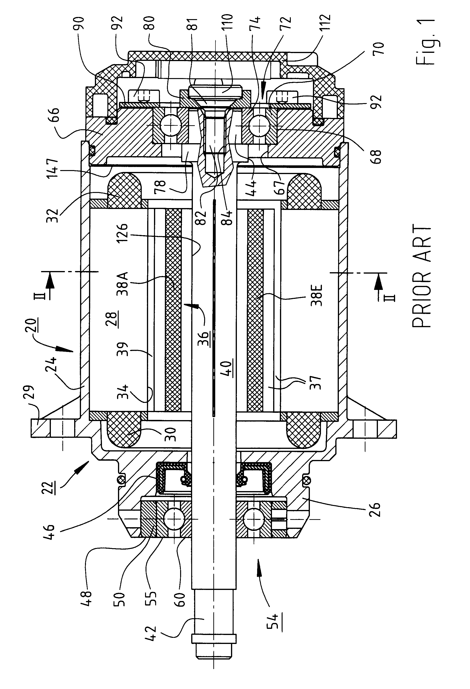
[0016]FIG. 1 shows an electronically commutated three-phase internal-rotor motor 20 having a housing 22 that comprises a cylindrical housing part 24, an A-side bell 26, and a mounting flange 29.

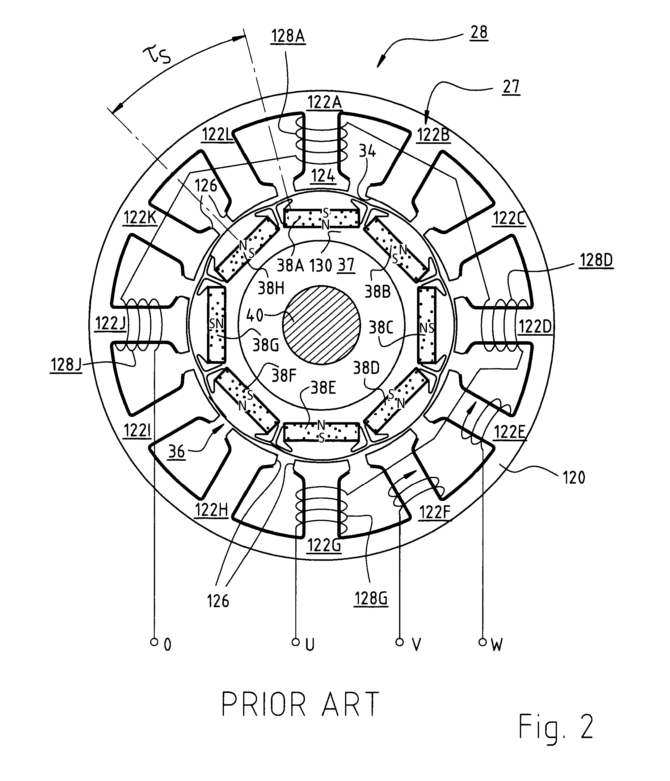
[0017]Arranged in cylindrical housing part 24 is a lamination stack 27 (FIG. 2) of an external stator 28 whose end windings are indicated at 30 and 32. Stator 28 has an internal recess 34 in which an eight-pole internal rotor 36, having a lamination stack 37 made up of laminations 41 (indicated schematically in FIG. 5) and having a total of eight permanent magnets 38A to 38H (see FIG. 2), is arranged on a shaft 40 whose drive end is labeled 42 and whos...


PUM


Abstract

A novel electric motor rotor structure, particularly desirable for use with brittle rare-earth-magnets, offers improved resistance to rattling and axial shifting. This is achieved by forming the rotor with an annular central yoke connecting to a plurality of pole shoes along the periphery of the rotor and defining a magnet-receiving recess or pocket 160 between each pole shoe and the central yoke. Spaced circumferentially between adjacent magnets 38 are regions 146 of reduced magnetic conductivity, which include relatively thin metallic holding segments, which connect adjacent pole shoes to each other and to the central yoke. During manufacturing, tools are applied to upset or crimp the holding segments, and thereby form spring elements, to hold the magnets in stable positions and resist any tendency of the magnets to rattle or axially shift during motor operation. One obtains the same power level from a smaller, and therefore lighter, motor than was previously possible.

Description

CROSS-REFERENCE This application claims priority of my German application DE 10 2010 023 159.2, filed 4 Jun. 2010, the content of which is incorporated by reference.FIELD OF THE INVENTION[0001]The present invention relates generally to an electric motor whose rotor includes permanent magnets and, more particularly, to an improved structure for mounting the magnets within the rotor. This motor is preferably implemented as an internal-rotor motor.BACKGROUND[0002]Because of their low axial moment of inertia, such motors are used for drive situations in which the motions of an electric motor must follow electrical instructions very quickly, for example for fast displacement of parts or for servo-assistance of motions. In a motor of this kind, the permanent magnets must not rattle, and also must not shift in an axial direction.SUMMARY OF THE INVENTION[0003]It is therefore an object of the invention to make available a novel electric motor structure with improved resistance to rattling an...

Claims


Application Information

Patent Timeline
IPC IPC(8): H02K1/28
CPCH02K1/276H02K15/03
Inventor ROMBACH, VOLKER
Owner EBM PAPST ST GEORGEN & -
Learn More