Synchronous machine starting device

a starting device and synchronous technology, applied in the direction of motor/generator/converter stopper, electric controller, dynamo-electric converter control, etc., can solve the problems of fragile mechanical distributor and easy noise, and achieve the effect of starting stably

Active Publication Date: 2011-12-08
TOSHIBA MITSUBISHI-ELECTRIC IND SYST CORP
View PDF2 Cites 7 Cited by
  • Summary
  • Abstract
  • Description
  • Claims
  • Application Information

AI Technical Summary

Benefits of technology

[0011]According to the present invention, a synchronous machine can be started stably.

Problems solved by technology

However, the mechanical distributor is fragile and is susceptible to noise due to a large amount of wiring.

Method used


Image

  • Synchronous machine starting device
  • Synchronous machine starting device
  • Synchronous machine starting device

Examples


first embodiment

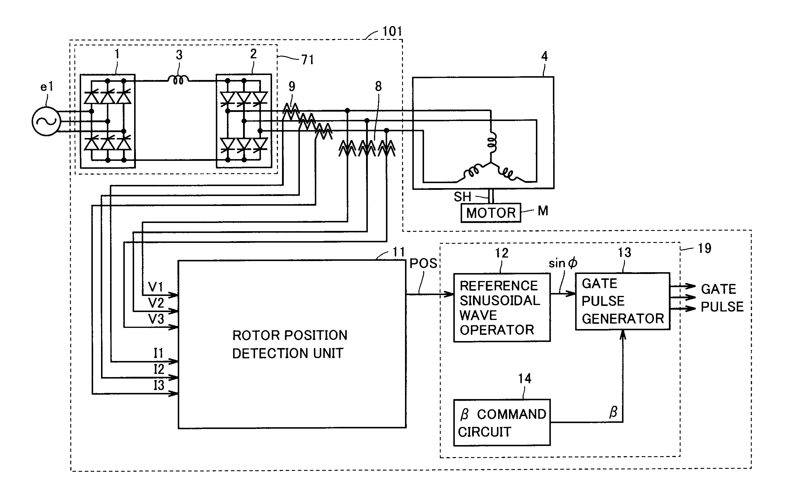
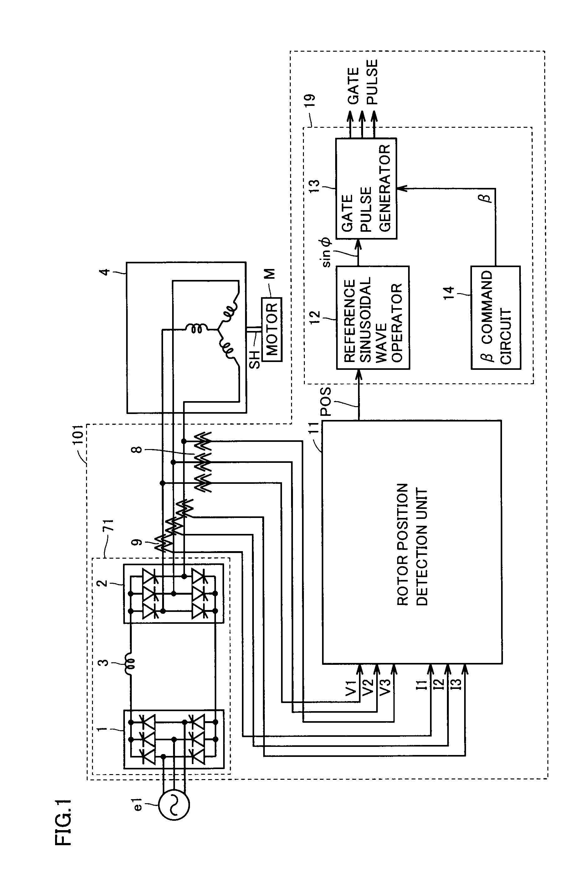
[0017]FIG. 1 is a diagram showing a configuration of a synchronous machine starting device in accordance with a first embodiment of the present invention.

[0018]Referring to FIG. 1, a synchronous machine starting device 101 includes a power conversion unit 71, an AC voltage detector 8, an AC current detector 9, a rotor position detection unit 11, and an inverter control unit (power conversion control unit) 19. Power conversion unit 71 includes a converter 1, an inverter 2, and a DC reactor 3. Inverter control unit 19 includes a reference sinusoidal wave operator 12, a gate pulse generator 13, and a β command circuit 14.

[0019]A synchronous machine 4 and a motor M are connected with each other via a shaft SH. Synchronous machine 4 is, for example, a synchronous generator or a synchronous motor and has an armature and a rotor. Motor M rotates at a prescribed speed when synchronous machine 4 is on standby. The rotational speed is low, for example, a few rpm. By contrast, the rotational s...

second embodiment

[0047]The present embodiment relates to a synchronous machine starting device which differs from the synchronous machine starting device in accordance with the first embodiment in that a high voltage circuit is eliminated. Except the description given below, it is similar to the synchronous machine starting device in accordance with the first embodiment.

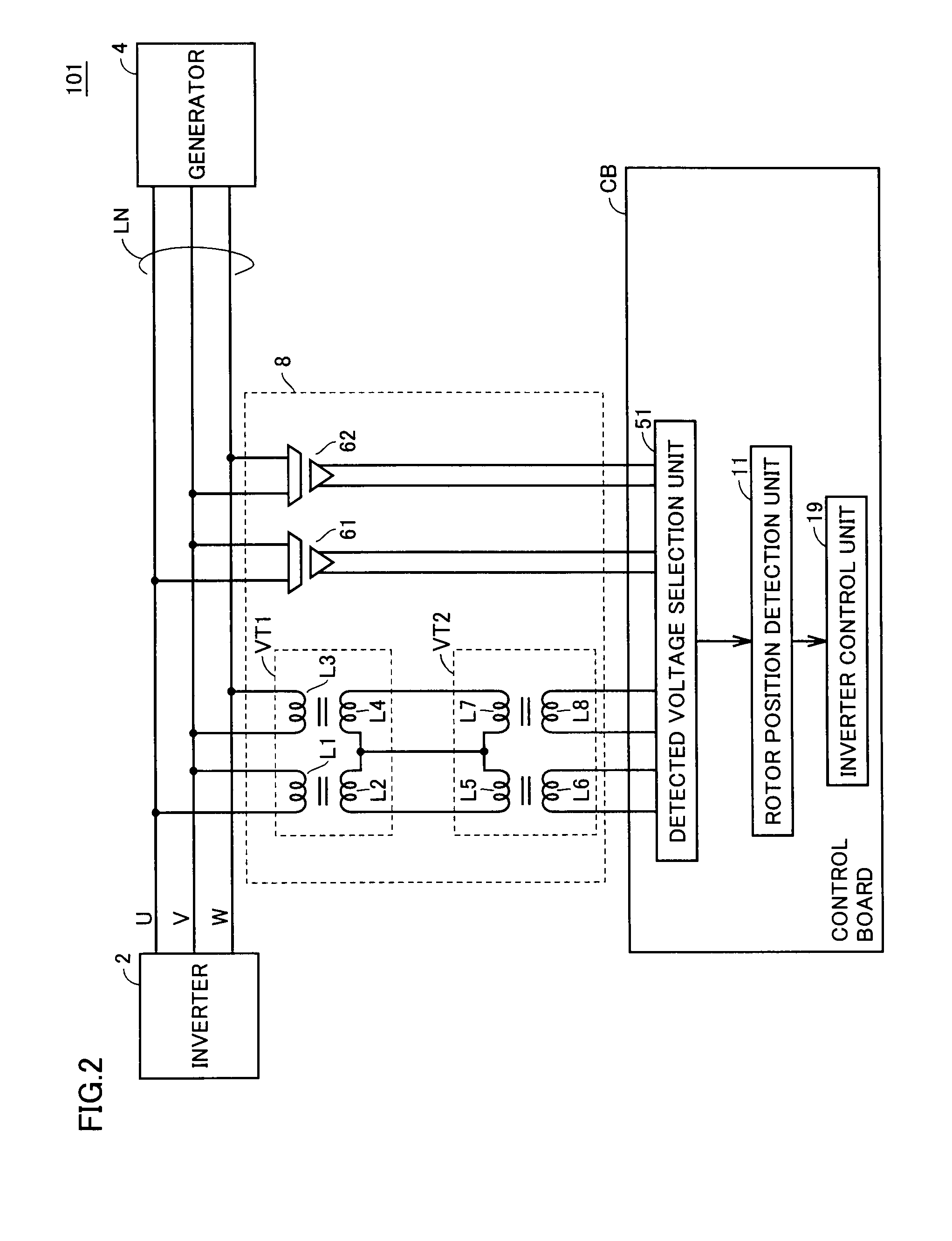
[0048]FIG. 3 is a diagram showing a configuration of a synchronous machine starting device in accordance with the second embodiment of the present invention.

[0049]Referring to FIG. 3, a synchronous machine starting device 102 differs from the synchronous machine starting device in accordance with the first embodiment of the invention in that AC voltage detector 8 is replaced by an AC voltage detector 58.

[0050]AC voltage detector 58 includes voltage transformers VT1, VT2 and clamping circuits CP1, CP2. Clamping circuit CP1 includes resistors R1, R2, R3 and Zener diodes ZD1, ZD2. Clamping circuit CP2 includes resistors R4, R5, R6 and Z...


PUM


Abstract

In a synchronous machine starting device, an AC voltage detection unit detects AC voltage supplied to an armature of a synchronous machine through an electric power line from a power conversion unit. The AC voltage detection unit has a first output end and a second output end isolated from the electric power line, transforms AC voltage supplied through the electric power line at a first ratio to output the transformed voltage from the first output end, and transforms AC voltage supplied through the electric power line at a second ratio and then limits the transformed voltage to a prescribed positive voltage value or lower and a prescribed negative voltage value or higher for output from the second output end. Then, a detected voltage selection unit selects one of the voltage received from the first output end and the voltage received from the second output end, and outputs the selected one to a rotor position detection unit. The rotor position detection unit detects a rotor position of the synchronous machine based on the voltage received from the detected voltage selection unit. A power conversion control unit controls the power conversion unit based on the detected rotor position.

Description

TECHNICAL FIELD[0001]The present invention relates to a synchronous machine starting device, and more particularly to a synchronous machine starting device which detects a rotor position of a synchronous machine.BACKGROUND ART[0002]Synchronous machine starting devices for starting synchronous machines such as generators and motors have been developed. Conventionally, a synchronous machine starting device uses a mechanical distributor which detects the position of a rotor of a synchronous machine, for example, by a proximity switch. However, the mechanical distributor is fragile and is susceptible to noise due to a large amount of wiring.[0003]Japanese Patent Laying-Open No. 2006-271038 (Patent Document 1) discloses an example of a synchronous machine starting device for eliminating the need for such a mechanical distributor. Specifically, this synchronous generator starting device includes an externally communicated converter formed of externally communicated devices such as thyrist...

Claims


Application Information

Patent Timeline
Patent Type & Authority Applications(United States)
IPC IPC(8): H02P6/20H02P1/52
CPCH02P1/46H02P6/182H02P9/08H02P9/009H02P2203/01
Inventor TAMAI, SHINZOFUJII, YOSUKEANDO, AKINOBUHOSOKAWA, YASUHIKO
Owner TOSHIBA MITSUBISHI-ELECTRIC IND SYST CORP
Why Eureka
Try Eureka