Liquid crystal display device and method for driving the same

a display device and liquid crystal technology, applied in the direction of instruments, computing, electric digital data processing, etc., can solve the problems of increasing power consumption and greatest power consumption of the tft configuring the output buffer unit, and achieve the effect of increasing the scan pulse time and improving image quality

Active Publication Date: 2011-12-08
LG DISPLAY CO LTD
View PDF6 Cites 8 Cited by
  • Summary
  • Abstract
  • Description
  • Claims
  • Application Information

AI Technical Summary

Benefits of technology

[0024]In the liquid crystal display device and the method for driving the same according to the embodiment of the present invention, each of the clock pulses is time-divided into p time-divisional clock pulses and the p time-divisional clock pulses are supplied to the stages of the gate driving unit. The stages are grouped into p blocks in correspondence with the time division of the clock pulses into the p time-divisional clock pulses, and the p blocks receive different time-divisional clock pulses. Accordingly, the load of the transmission lines, through which the time-divisional clock pulses are supplied to the pull-up switching elements of the stages, is reduced to 1 / p that of the case where the clock pulses are supplied to the pull-up switching elements of the stages without being time-divided. Then, the capacitance of the parasitic capacitor generated in the pull-up switching elements is reduced to 1 / p that of the case where the clock pulses are supplied to the pull-up switching elements of the stages without being time-divided and thus the power consumption of the gate driving unit is reduced to 1 / p that of the case where the clock pulses are supplied to the pull-up switching elements of the stages without being time-divided.
[0025]In addition, when the capacitance of the parasitic capacitor generated in the pull-up switching elements is reduced to 1 / p that of the case where the clock pulses are supplied to the pull-up switching elements of the stages without being time-divided, the rising times of the scan pulses are decreased according to a time constant RC and thus image quality can be improved.

Problems solved by technology

At this time, the power consumption of the TFT configuring the output buffer unit is greatest in the gate driving unit.
As a result, power consumption is increased.

Method used


Image

  • Liquid crystal display device and method for driving the same
  • Liquid crystal display device and method for driving the same
  • Liquid crystal display device and method for driving the same

Examples


Embodiment Construction

[0039]Hereinafter, a liquid crystal display device and a method for driving the same according to an embodiment of the present invention will be described in detail with reference to the accompanying drawings.

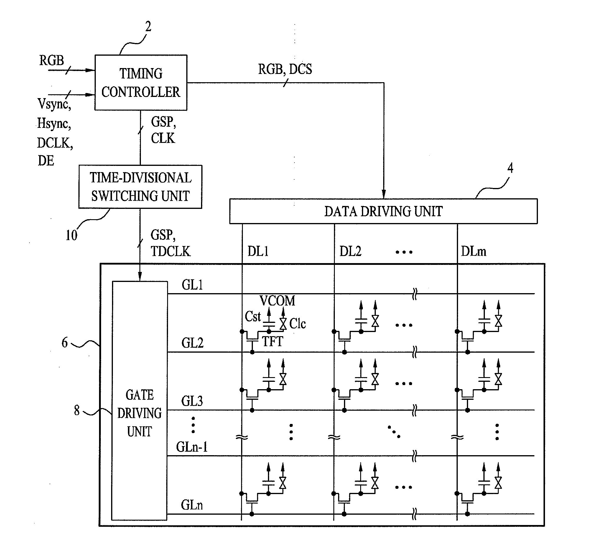
[0040]FIG. 1 is a diagram showing the configuration of a liquid crystal display device according to an embodiment of the present invention.

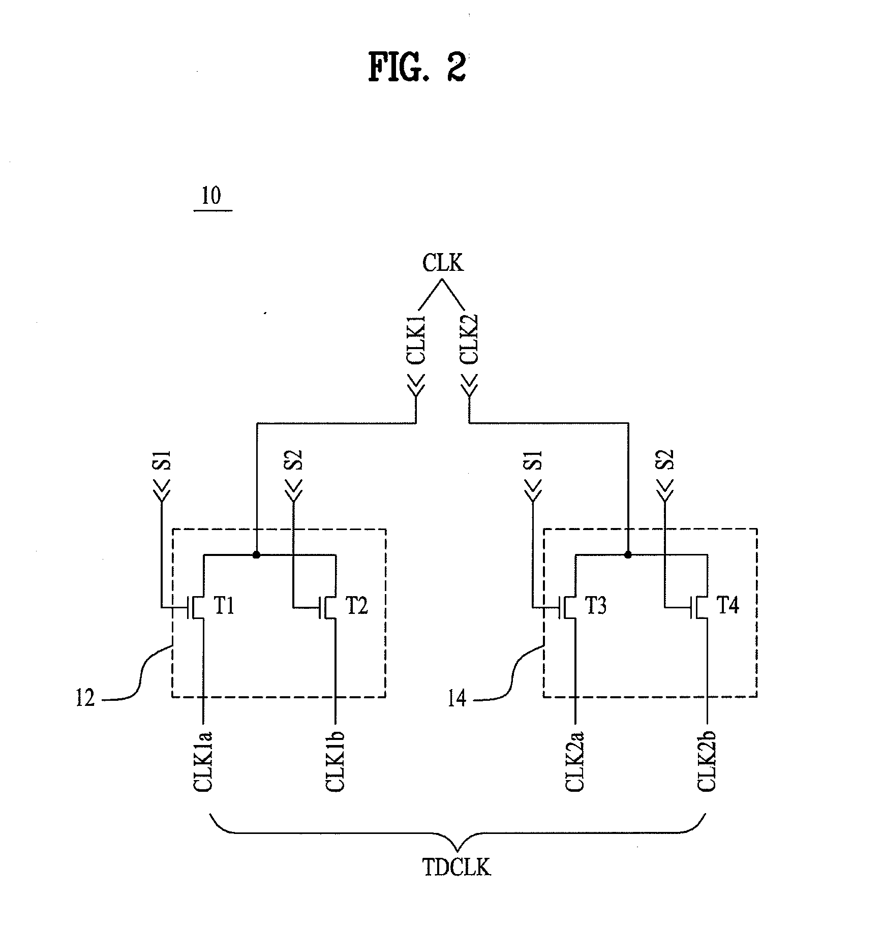
[0041]The liquid crystal display device shown in FIG. 1 includes a liquid crystal panel 6, a timing controller 2, a data driving unit 4, a time-divisional switching unit 10, and a gate driving unit 8. The gate driving unit 8 is mounted in the liquid crystal panel 6.

[0042]The liquid crystal panel 6 includes a plurality of gate lines GL1 to GLn and a plurality of data lines DL1 to DLm. The plurality of gate lines GL1 to GLn and the plurality of data lines DL1 to DLm define respective pixel regions. Each pixel region includes a Thin Film Transistor (TFT), and a liquid crystal capacitor Clc and a storage capacitor Cst connected to the TFT. The l...


PUM


Abstract

A liquid crystal display device capable of reducing power consumption of a gate driving circuit and a method for driving the same are discussed. The liquid crystal display device includes a liquid crystal panel including pixel regions defined by gate lines and data lines, a timing controller for outputting a plurality of data control signals, a plurality of clock pulses and a start pulse, a time-divisional switching unit for time-dividing the plurality of clock pulses and outputting time-divisional clock pulses, a data driving unit for driving the data lines according to the plurality of data control signals, and a gate driving unit including a plurality of stages for sequentially outputting scan pulses according to the start pulse and the plurality of time-divisional clock pulses, wherein the stages receive the time-divisional clock pulses in units of blocks and each of the time-divisional clock pulses supplied to the blocks is different.

Description

[0001]This application claims the benefit of Korean Patent Application No. 10-2010-0053257, filed on Jun. 7, 2010, which is hereby incorporated by reference as if fully set forth herein.BACKGROUND OF THE INVENTION[0002]1. Field of the Invention[0003]The present invention relates to a liquid crystal display device, and more particularly, to a liquid crystal display device capable of reducing power consumption of a gate driving circuit, and a method for driving the same.[0004]2. Discussion of the Related Art[0005]Recently, as display devices for mobile devices, liquid crystal display devices are widely used due to excellent image quality, weight reduction, slimness and low power consumption.[0006]A Gate In Panel (GIP) type liquid crystal display device, in which a gate driving circuit is mounted in a panel so as to realize a small volume, weight reduction and low manufacturing cost, has been introduced.[0007]In the GIP type liquid crystal display device, the gate driving circuit using...

Claims


Application Information

Patent Timeline
Patent Type & Authority Applications(United States)
IPC IPC(8): G09G5/00G09G3/36
CPCG09G2310/08G09G3/3677
Inventor SEO, HYE-RIMSHIN, CHEON-KEECHAE, JI-EUN
Owner LG DISPLAY CO LTD
Why Eureka
Try Eureka