Portable computing device with a saw-less transceiver

a technology of transceivers and computing devices, applied in the field of wireless communication, can solve problems such as the difficulty of re-designing analog parts, and achieve the effect of improving the quality of analog parts

Active Publication Date: 2011-12-08
AVAGO TECH INT SALES PTE LTD
View PDF5 Cites 10 Cited by
  • Summary
  • Abstract
  • Description
  • Claims
  • Application Information

AI Technical Summary

Problems solved by technology

Redesigning the analog portions, however, is not a straightforward task since most anal

Method used


Image

  • Portable computing device with a saw-less transceiver
  • Portable computing device with a saw-less transceiver
  • Portable computing device with a saw-less transceiver

Examples


Embodiment Construction

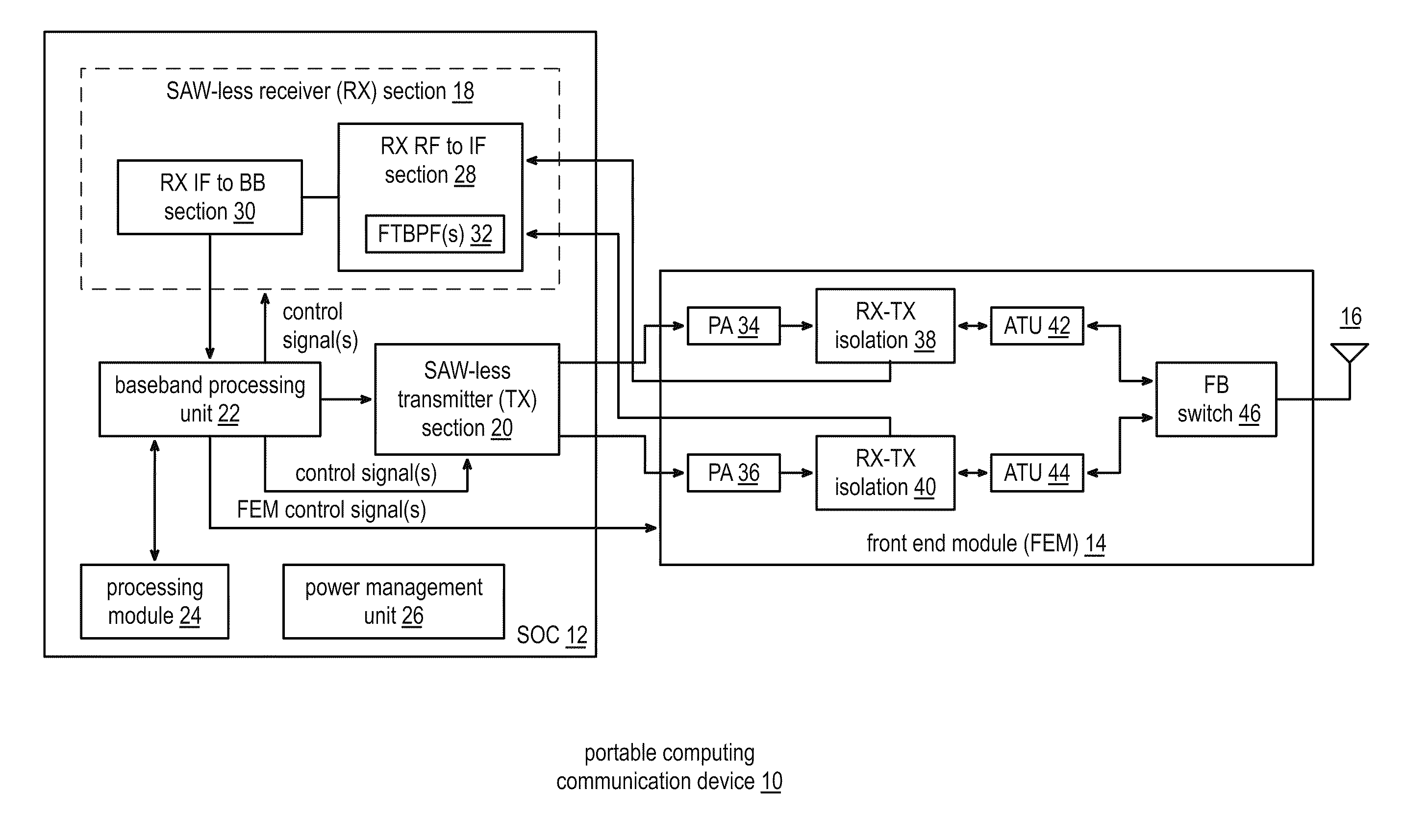
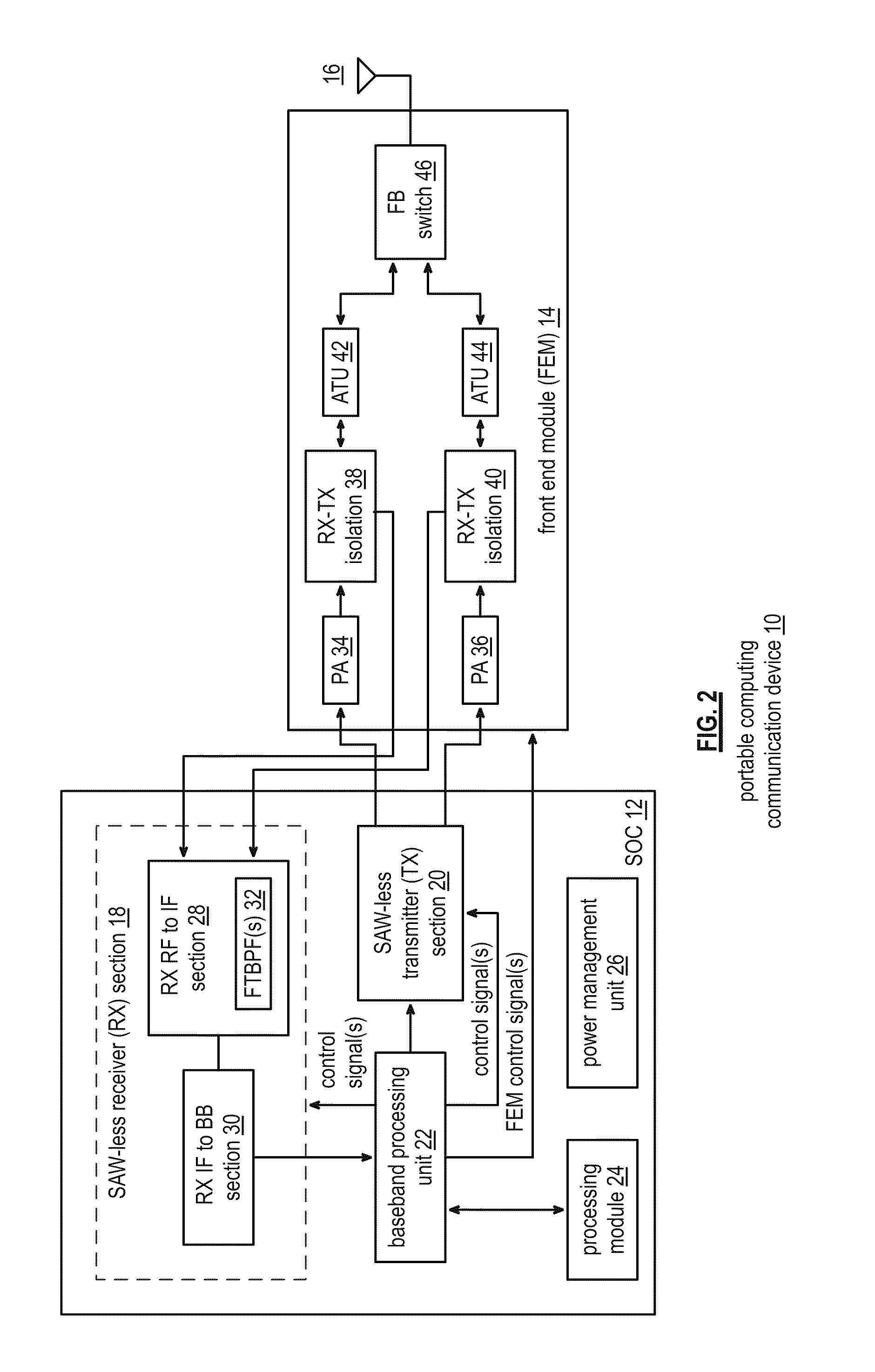
[0130]FIG. 2 is a schematic block diagram of an embodiment of a portable computing communication device 10 that includes a system on a chip (SOC) 12 and a front-end module (FEM) 14, which may be implemented on separate integrated circuits. The portable computing communication device 10 may be any device that can be carried by a person, can be at least partially powered by a battery, includes a radio transceiver (e.g., radio frequency (RF) and / or millimeter wave (MMW)) and performs one or more software applications. For example, the portable computing communication device 10 may be a cellular telephone, a laptop computer, a personal digital assistant, a video game console, a video game player, a personal entertainment unit, a tablet computer, etc.

[0131]The SOC 12 includes a SAW-less receiver section 18, a SAW-less transmitter section 20, a baseband processing unit 22, a processing module 24, and a power management unit 26. The SAW-less receiver 18 includes a receiver (RX) radio frequ...


PUM


Abstract

A portable computing device includes an FEM, a SAW-less receiver, a SAW-less transmitter, and a baseband processing unit. The FEM isolates one or more outbound RF signals from one or more inbound RF signals. The SAW-less receiver converts the one or more inbound RF signals into one or more inbound intermediate frequency (IF) signals by frequency translating a baseband filter response to an IF filter response and/or an RF filter response. The SAW-less receiver filters the inbound RF signal(s) in accordance with the RF filter response and/or filters the inbound IF signal(s) in accordance with the IF filter response. The SAW-less receiver then converts the inbound IF signal(s) into inbound symbol stream(s). The SAW-less transmitter converts outbound symbol stream(s) into the outbound RF signal(s). The baseband processing unit converts outbound data into the outbound symbol stream(s) and convert the inbound symbol stream(s) into inbound data.

Description

CROSS REFERENCE TO RELATED PATENTS[0001]This patent application is claiming priority under 35 U.S.C §120 as a continuation-in-part patent application of co-pending patent application entitled, “SAW-LESS RECEIVER WITH OFFSET RF FREQUENCY TRANSLATED BPF,” having a filing date of Mar. 24, 2011, and a serial number of 13 / 070,980 (Attorney Docket No. BP22165), and which claims priority under 35 U.S.C. §119(e) to a provisionally filed patent application entitled, “CONFIGURABLE AND SCALABLE RF FRONT-END MODULE,” having a provisional filing date of Jun. 3, 2010, and a provisional Ser. No. 61 / 351,284 (Attorney Docket No. BP21922), pending, all of which are incorporated herein by reference in their entirety and made part of the present U.S. Utility patent application for all purposes.STATEMENT REGARDING FEDERALLY SPONSORED RESEARCH OR DEVELOPMENT[0002]Not applicableINCORPORATION-BY-REFERENCE OF MATERIAL SUBMITTED ON A COMPACT DISC[0003]Not applicableBACKGROUND OF THE INVENTION[0004]1. Technic...

Claims


Application Information

Patent Timeline
IPC IPC(8): H04W88/02
CPCH03D7/1441H03D7/1458H03D7/1466H04B1/109H04B1/40H03D2200/009H03D7/1483H03D7/165H03D2200/0025H03D2200/0084H03D2200/0088H03D7/1433
Inventor DARABI, HOOMAN
Owner AVAGO TECH INT SALES PTE LTD
Why Eureka
Try Eureka