Resonance modifying connector

a technology of resonance characteristics and connectors, applied in the field of connectors, can solve the problems of system configuration of differential signal pairs that may experience performance degradation, unsuitable for use in higher speed applications, and the size of the connector has a greater influence on the performance of the connector

Active Publication Date: 2011-12-08
MOLEX INC
View PDF6 Cites 99 Cited by
  • Summary
  • Abstract
  • Description
  • Claims
  • Application Information

AI Technical Summary

Benefits of technology

[0005]A connector includes a housing that supports a plurality of ground and signal terminals. The terminals can have contact portions, tail portions and body portions extending between the contact and tail portions. The terminals can be positioned in wafers. The signal terminals can be provided as a pair of signal terminals in adjacent wafers that are used as a differential signal pair. A bridge is extends between two adjacent ground terminals while extending transversely and not in contact with signal terminals positioned between the ground terminals. If desired, multiple bridges may be used. In one embodiment, the bridge can be a pin that is inserted through multiple wafers and may extend transversely past a plurality of pairs of differential signal pairs. In another embodiment, the bridge can be a series of clips that are positioned in the wafers so as to allow each clip to engage a clip in an adjacent wafer. If the bridge is a pin, the pin can be inserted through a first side of the connector, pass through multiple wafers and extends to a second side of the connector. While a single bridge can couple three or more ground terminals, in an embodiment a first bridge can be used to couple a first pair of ground terminals and a second bridge can be used to couple a second pair of ground terminals, even if the first and second pair of ground terminals share a terminal. The ground terminals can include translatable arms that are deflected when the bridge engages the ground terminals.

Problems solved by technology

An increasingly significant issue is that as the frequency of the signals increases (so as to increase the effective data rates), the size of the connector has a greater influence on the performance of the connector.
Thus, even connector systems configured to use differential signal pairs may experience degradation of performance as operating frequencies increase.
Potential resonance conditions in existing connectors tend to make them unsuitable for use in higher speed applications.

Method used


Image

  • Resonance modifying connector
  • Resonance modifying connector
  • Resonance modifying connector

Examples


Embodiment Construction

[0050]As required, detailed embodiments are disclosed herein; however, it is to be understood that the disclosed embodiments are merely exemplary and the depicted features may be embodied in various forms. Therefore, specific details disclosed herein are not to be interpreted as limiting, but merely as a basis for the claims and as a representative basis for teaching one skilled in the art to variously employ the disclosed features in virtually any appropriate manner, including employing various features disclosed herein in combinations that might not be explicitly described.

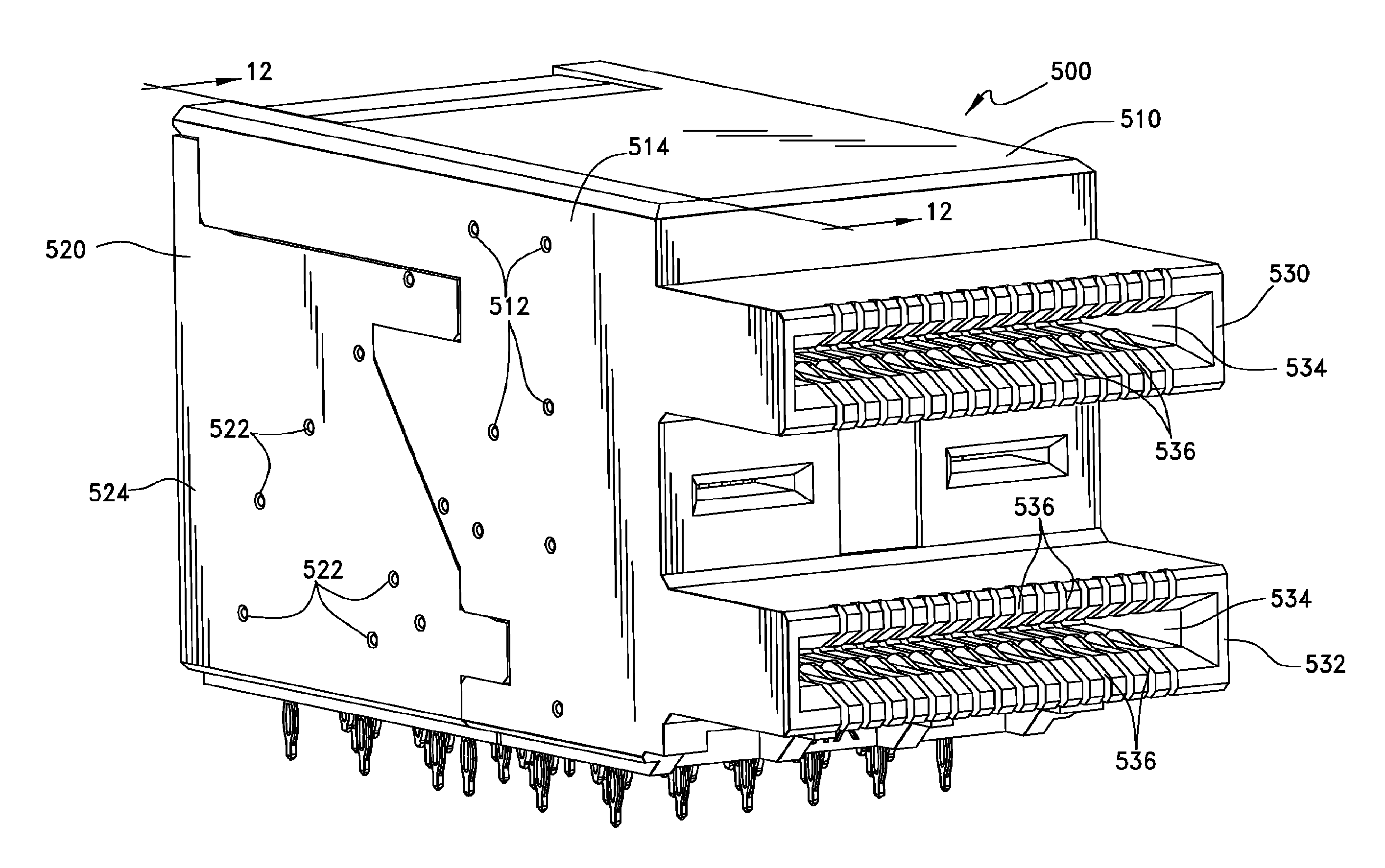
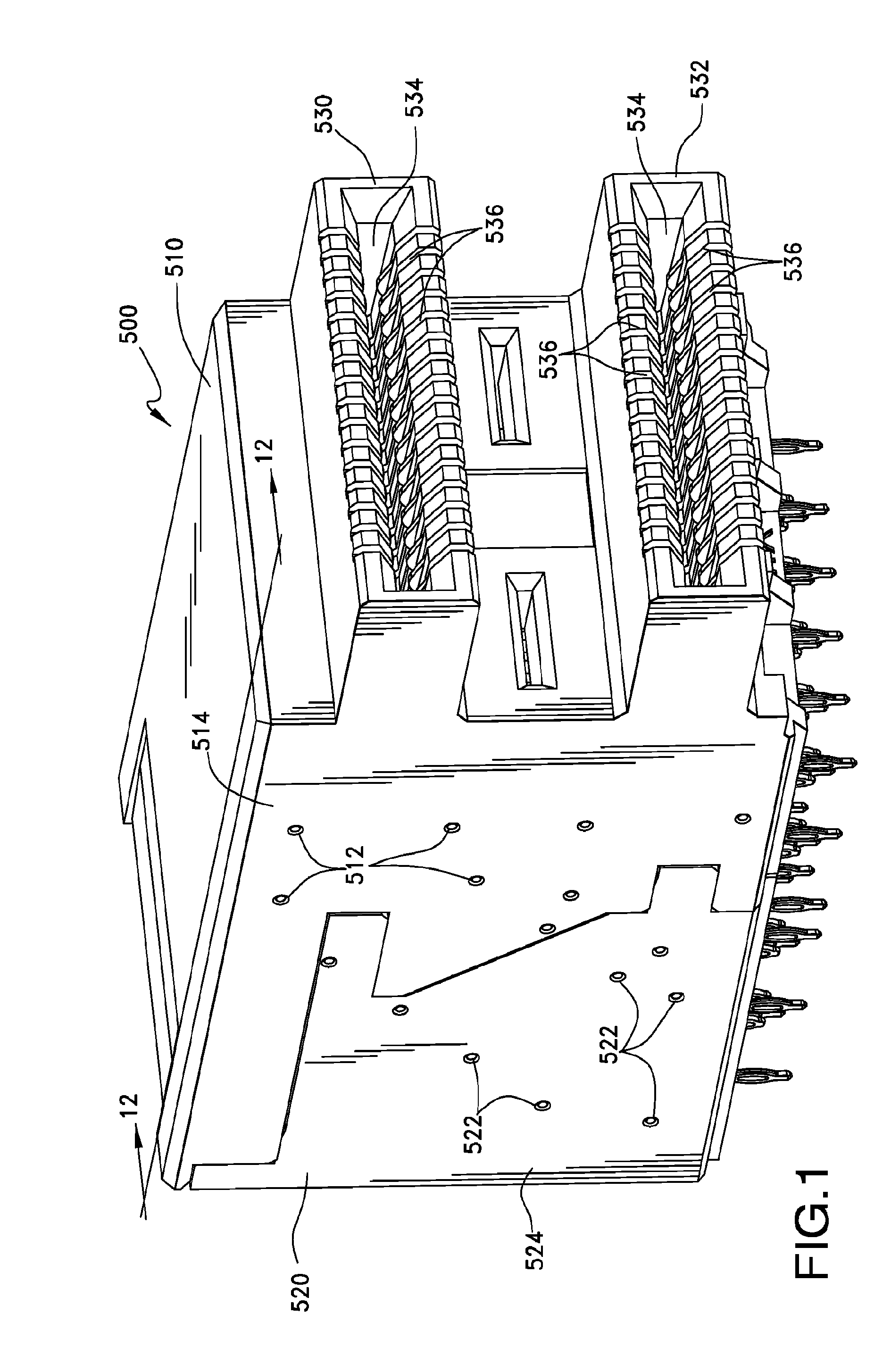
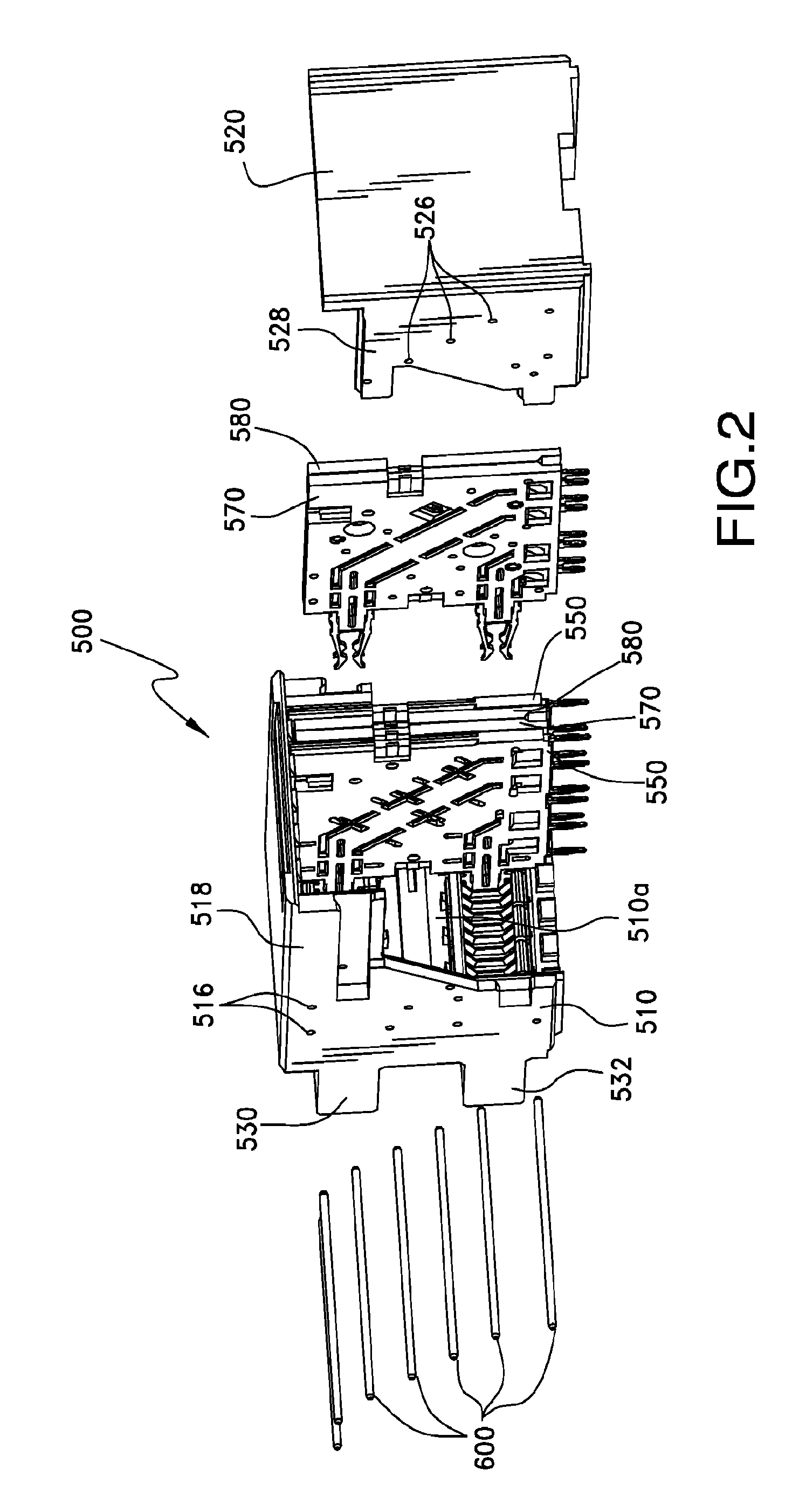
[0051]Small form pluggable (SFP) style connectors are often used in systems where an input / output (I / O) data communication channel is desired. A number of variations in SFP-style connectors exist and different connectors are configured to meet different specifications, such as specifications commonly known as SFP, XFP, QSFP, SFP+ and the like. In general, the SFP-style connectors are configured to mate to module...


PUM

PropertyMeasurementUnit
diameteraaaaaaaaaa
diameteraaaaaaaaaa
resonant frequencyaaaaaaaaaa

Abstract

A connector assembly is provided that is suitable for modifying the resonant frequency of ground terminals used in conjunction with high data rate signal terminals. Ground terminals may be interconnected with a conductive bridge so as to provide ground terminals with a predetermined maximum effective electrical length. Reducing the effective electrical length of the ground terminal can move the resonance frequencies of the connector outside the operational range of frequencies at which signals will be transmitted.

Description

RELATED APPLICATIONS[0001]This application is a national phase of PCT Application No. PCT / US09 / 67333, filed Dec. 9, 2009, which in turn claims priority to United States Provisional Appln. Serial No. 61 / 122,216, filed Dec. 12, 2008, both of which are incorporated herein by reference in their entirety.FIELD OF INVENTION[0002]The present invention generally relates to connectors suitable for high data rate communications and, more particularly, to a connector with improved resonance characteristics.BACKGROUND OF THE INVENTION[0003]While a number of different configurations exist for high data rate connectors, one common configuration is to align a number of terminals in a row so that each terminal is parallel to an adjacent terminal. It is also common for such terminals to be closely spaced together, such as at a 0.8 mm pitch. Thus, high data rate connectors tend to include a number of tightly spaced and similarly aligned terminals.[0004]High data rate communication channels tend to us...

Claims


Application Information

Patent Timeline
Patent Type & Authority Applications(United States)
IPC IPC(8): H01R24/00H01R43/20
CPCH01R29/00H01R31/08H01R13/6471Y10T29/49208H01R13/6586H01R43/20H01R13/646H01R13/6474
Inventor REGNIER, KENT E.CASHER, PATRICK R.LONG, JERRY A.
Owner MOLEX INC
Why Eureka
Try Eureka