Guidewire

a technology of guidewires and lesion locations, applied in the field of guidewires, can solve the problems of inability to accurately measure a lesion, inability to and inability to measure a lesion, so as to achieve accurate measurement of the lesion location and prevent a vessel from perforating

Inactive Publication Date: 2011-12-08
ASAHI INTECC CO LTD
View PDF6 Cites 16 Cited by
  • Summary
  • Abstract
  • Description
  • Claims
  • Application Information

AI Technical Summary

Benefits of technology

[0010]The present invention has been made to solve the foregoing problems, and an object of the present invention is to provide a guidewire capable of preventing perforation of a vessel or the like, measuring a peripheral portion of a tubular organ such as a vessel, and performing accurate measurement of a lesion location even under heartbeats.

Problems solved by technology

Hence, since the front end of the guidewire is hardened, this front end may perforate a vessel or the like.
This causes a problem of not being able to measure a lesion location at the peripheral portion of the tubular organ such as a vessel by the markers.
This also causes a problem of not being able to perform accurate measurement.
This drastically increases the stiffness of the coil part fixed by laser welding or the like.
Accordingly, this guidewire cannot solve the problems caused by the technique described in JP-T-7-500749, either.

Method used


Image

  • Guidewire
  • Guidewire
  • Guidewire

Examples


first embodiment

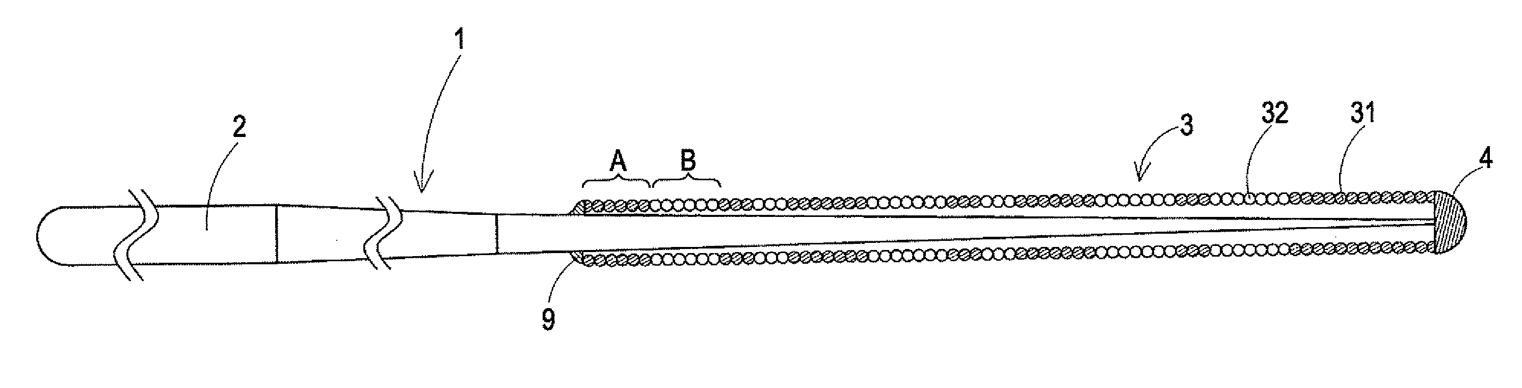
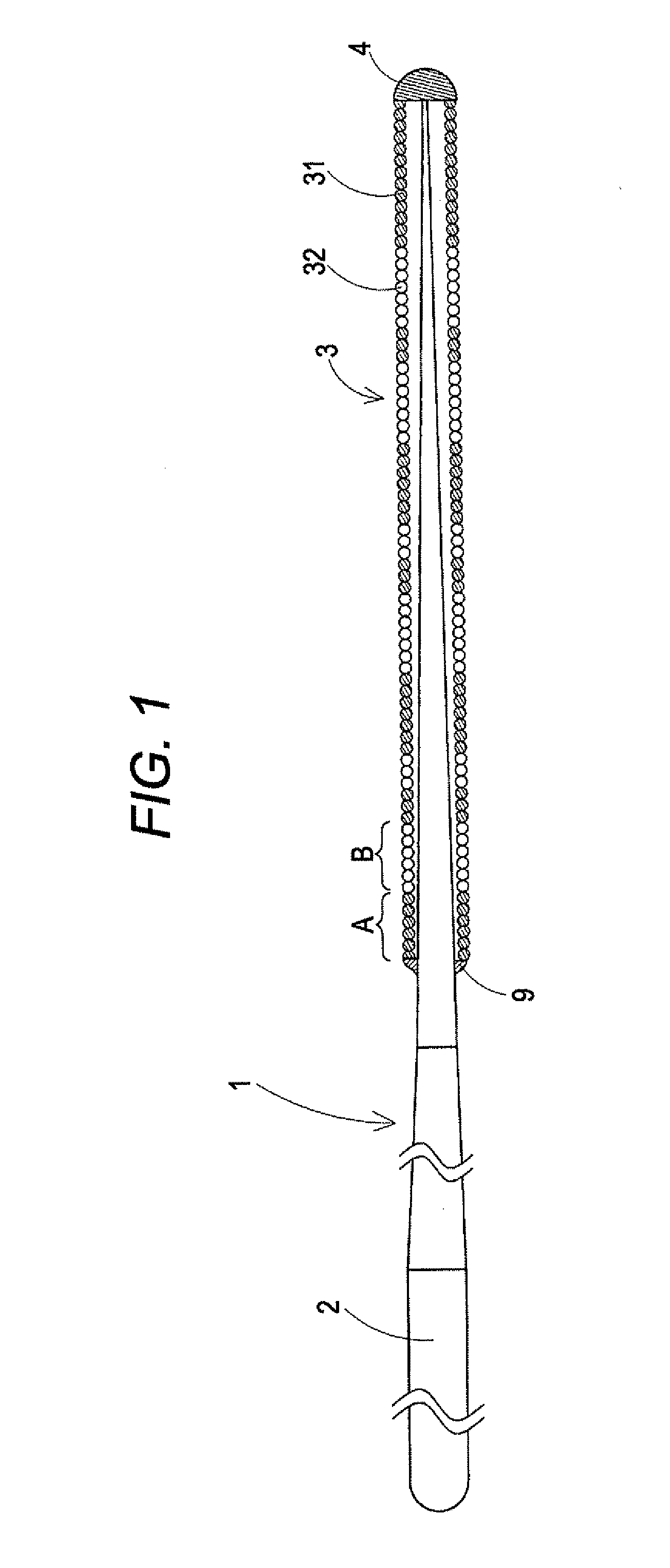
[0044]FIG. 1 illustrates an overall view of a guidewire according to a first embodiment of the invention.

[0045]It is noted that, in FIG. 1, the left side is referred to as “a proximal side,” and the right side is referred to as “a front side” for convenience of explanation.

[0046]Also, in FIG. 1, a guidewire 1 is shortened in the longitudinal direction to show the entirety schematically for ease of understanding. Accordingly, the entire dimension differs from the actual one.

[0047]In FIG. 1, the guidewire 1 has a core shaft 2 and a coiled body 3 covering the tip portion of the core shaft 2. The tip portion of the core shaft 2 and the tip portion of the coiled body 3 are fixed at a most distal portion 4. The proximal portion of the coiled body 3 is fixed to the core shaft 2 by a brazed portion 9 at a position on the proximal side of the most distal portion 4.

[0048]A material for the core shaft 2 is not particularly limited but can be a material such as stainless steel (SUS 304), a supe...

second embodiment

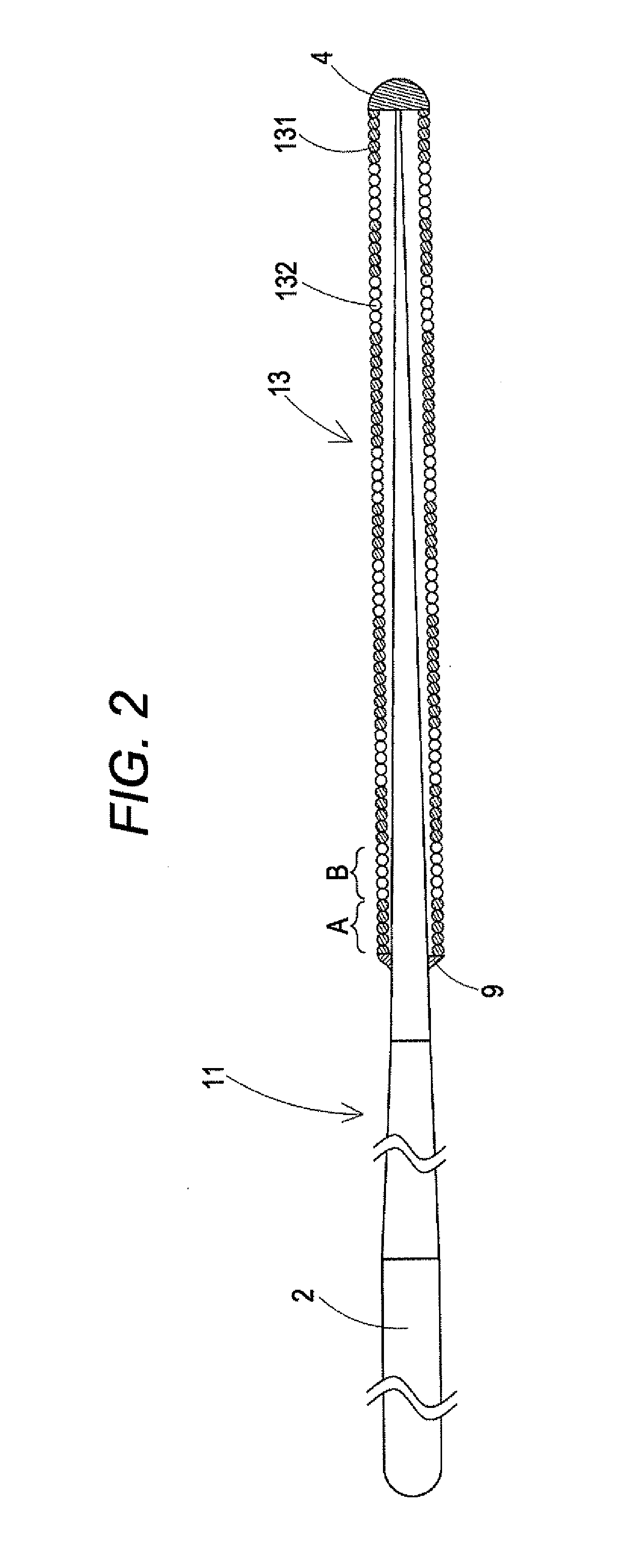
[0063]Next, a guidewire according to a second embodiment will be described with reference to FIG. 2 mainly on the difference from the first embodiment.

[0064]In FIG. 2 as well as in FIG. 1, a guidewire 11 is shortened in the longitudinal direction to show the entirety schematically for ease of understanding. Accordingly, the entire dimension differs from the actual one.

[0065]A coiled body 13 of the guidewire 11 is formed by arranging a radiopaque coil of strand 131 and a radiolucent coil of strand 132 alternately in line and connecting them with each other. The radiolucent coils of strand 132 are formed to have equal lengths to one another. Thus, radiolucent portions B have equal lengths to one another. Hence, the distances between radiopaque portions A are uniform. Accordingly, a lesion location can be measured accurately.

[0066]Meanwhile, the length of the radiopaque portion A can be changed in accordance with a lesion location for which the guidewire is to be used. The length of a ...

third embodiment

[0067]Next, a guidewire according to a third embodiment will be described with reference to FIG. 3 mainly on the difference from the first embodiment.

[0068]In FIG. 3 as well as in FIG. 1, a guidewire 21 is shortened in the longitudinal direction to show the entirety schematically for ease of understanding. Accordingly, the entire dimension differs from the actual one.

[0069]A coiled body 23 of the guidewire 21 is formed by arranging a radiopaque coil of strand 231 and a radiolucent coil of strand 232 alternately in line and connecting them with each other. As shown in FIG. 3, the radiopaque coil of strand 231 constituting a radiopaque portion A and the radiolucent coil of strand 232 constituting a radiolucent portion B have equal lengths. Thus, the distances between the radiopaque portions A (the lengths of the radiolucent portions B) are equal to one another, and the lengths of the radiopaque portions A are equal to one another. Accordingly, a lesion location can be measured more ac...


PUM


Abstract

An object of the present invention is to provide a guidewire capable of measuring a lesion location present in a vascular channel, preventing perforation of a vessel or the like by improving flexibility of a lesion measuring part, measuring a lesion of a peripheral portion by improving insertability of the guidewire into the peripheral portion of a tubular organ such as a vessel, and accurately measuring a lesion location inside a vascular channel even under heartbeats. The guidewire includes a core shaft and a coiled body wound around a front end of the core shaft. The coiled body is made of a coil of strand. The coil of strand is formed by arranging a radiopaque coil of strand and a radiolucent coil of strand alternately in line and connecting them with each other.

Description

CROSS REFERENCE TO RELATED APPLICATIONS[0001]This application is based on Japanese Patent Application No. 2010-127792 filed with the Japan Patent Office on Jun. 3, 2010, the entire content of which is hereby incorporated by reference.TECHNICAL FIELD[0002]The present invention relates to a guidewire.BACKGROUND ART[0003]Conventionally, various kinds of guidewires inserted in a tubular organ such as a vessel, a digestive tract, or a ureter or an intracorporeal tissue for use in measurement of a lesion location have been proposed.[0004]For example, JP-T-7-500749 describes a guidewire with a measurement function in which a string of radiopaque markers is fixed at a front end of the guidewire by bonding by adhesive, welding, or soldering.[0005]In a guidewire described in JP-T-10-513081, a radiolucent proximal end coil and a radiopaque distal end coil are provided at least at a tip portion of an elongated wire. A front end of the proximal end coil and a proximal end of the distal end coil ...

Claims


Application Information

Patent Timeline
Patent Type & Authority Applications(United States)
IPC IPC(8): A61M25/09
CPCA61M25/09A61M2025/09166A61M2025/09133A61M2025/09083
Inventor TSUNEZUMI, ATSUSHI
Owner ASAHI INTECC CO LTD
Why Eureka
Try Eureka