Self-organizing circuits

a self-organizing circuit and circuit technology, applied in the field of self-organizing circuits, can solve the problems of inability to deal with imperfection, inability to realize the self-organization of nature, and the inability to solve problems such as the inability to solve imperfection, etc., and achieve the effect of avoiding the cycle of current paradigms and avoiding the cycle of self-organization

Inactive Publication Date: 2011-12-08
KNOWM TECH
View PDF4 Cites 8 Cited by
  • Summary
  • Abstract
  • Description
  • Claims
  • Application Information

AI Technical Summary

Benefits of technology

[0018]The dendritic unit can be composed of volatile functional memory. In other words, the volatile memory configures a functional state. Energy needed for the repair of the volatile functional state comes from the energy source units. The axonal unit broadcasts the output state of the dendritic unit to other circuit modules within the fabric. The axonal links are bi-directional, enabling the axonal unit to sum a measure of flow. For example, the axonal unit could sum the combined strength of its plastic output connections or measure the average current sourced and / or sunk. The axonal unit is used to gate the dendritic units access to the energy unit. Some subset of circuit modules are connected to data outputs. The data outputs must have an effect within an environment, causing a change in the sensory input. That is, the circuit fabric must be embedded within an environment.

Problems solved by technology

The electronics industry does not yet understand how nature self-organizes.
As chip feature lengths become smaller and wafers become larger, the inability to deal with imperfection begins to consume substantially more resources.
Unfortunately most are trapped in the cycle of their current paradigm for example constructing algorithms that they will run on specialized hardware.
However, the application space is so large it is difficult to see.

Method used


Image

  • Self-organizing circuits
  • Self-organizing circuits
  • Self-organizing circuits

Examples


Embodiment Construction

[0035]The particular values and configurations discussed in these non-limiting examples can be varied and are cited merely to illustrate at least one embodiment and are not intended to limit the scope thereof.

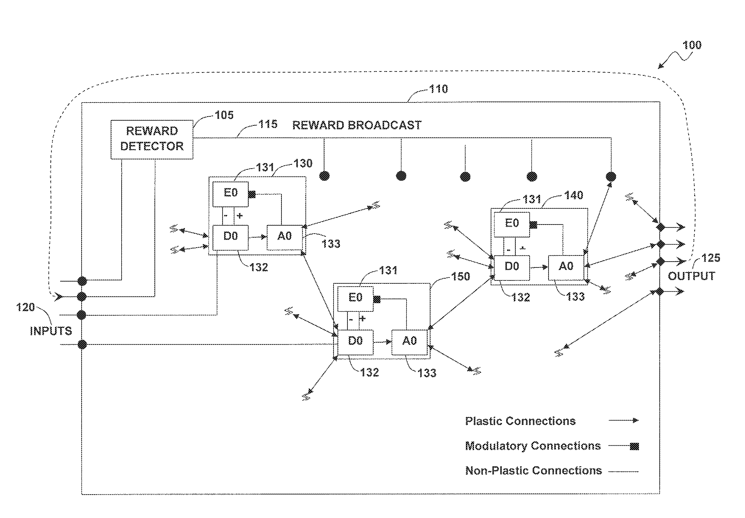
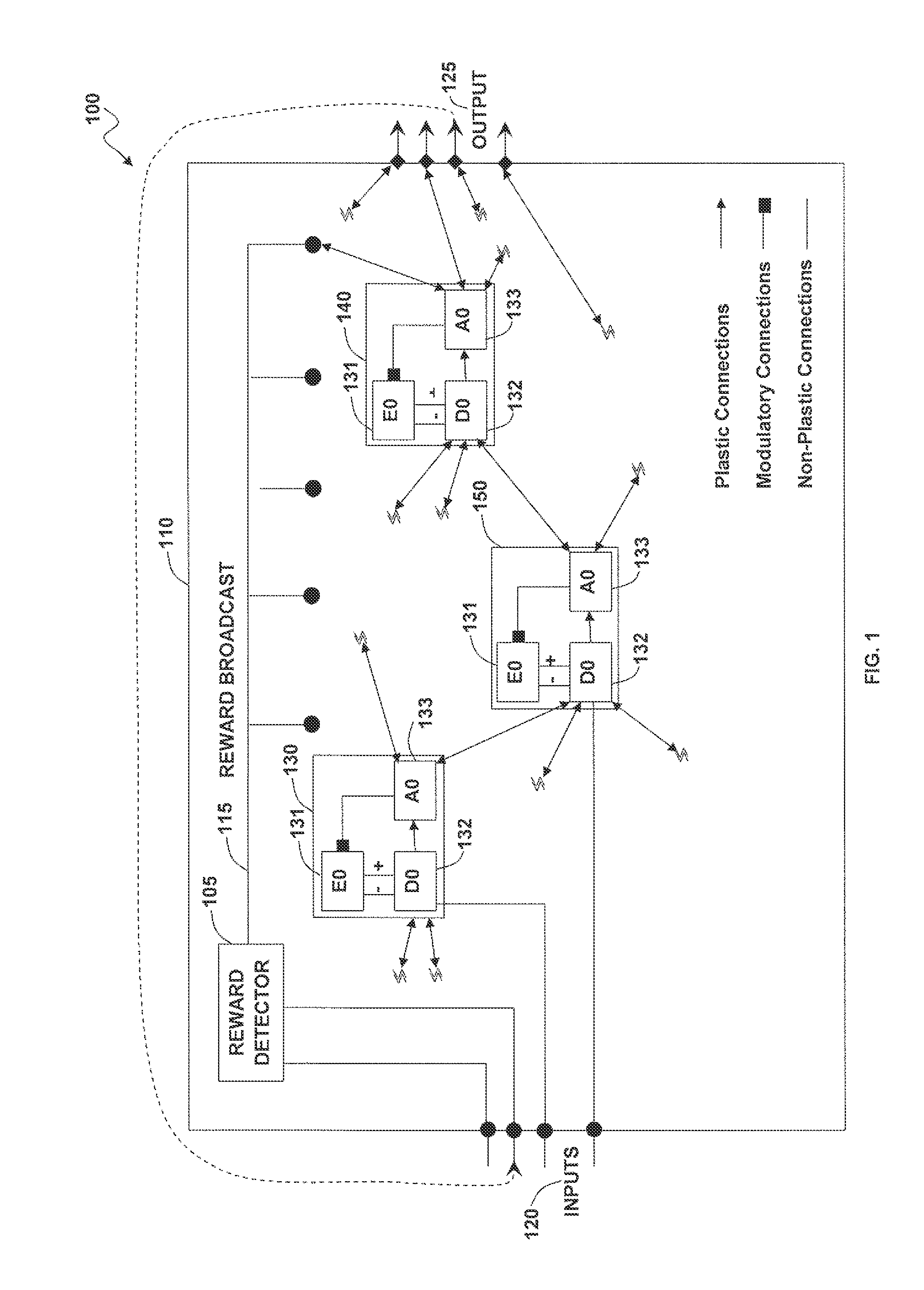
[0036]FIG. 1 illustrates a schematic diagram of self-organizing circuit fabric 100, in accordance with the disclosed embodiments. Sensor inputs 120 are mapped to a number of circuit modules 130, 140 and 150 embedded in the fabric 100. A portion of the inputs 120 are mapped to a reward detector 105, which generates a reward signal 115 when it detects specific regularities in the input data stream, for example the smile of a human. The reward signal 115 is duplicated and broadcast throughout the fabric 100. Each circuit modules 130, 140 and 150 contain a dendritic unit 132 an axonal unit 133 and an energy unit 131. The dendritic unit 132 is composed of volatile functional memory. In other words, the volatile memory configures a functional state.

[0037]Energy needed for the repair ...


PUM


Abstract

A self-organizing electronic system and method that organizes and repairs itself. A number circuit of modules can be embedded in a fabric. Each circuit module can calculate some function of its inputs and produces an output, which is encoded on volatile memory held together by a plasticity rule. The plasticity rule allows circuit modules to converge to any possible functional state defined by the structure of the information being processed. Flow through the system gates energy dissipation of the individual circuit modules. Circuit modules receiving high flow become locked in their functional states while circuit modules receiving little or no flow mutate in search of better configurations. These principles can be utilized to configure the state of any functional element within the system, and can be abstracted to higher levels of organization. Far from expending energy on state configurations, a volatile system only expends energy stabilizing successful configurations. Continuous stabilization coupled with redundancy results in a circuit capable of healing itself from the bottom-up.

Description

CROSS-REFERENCE TO PROVISIONAL APPLICATION[0001]This nonprovisional patent application claims the benefit under 35 U.S.C.§119(e) of U.S. Provisional Patent Application Ser. No. 61 / 352,490 filed on Jun. 8, 2010, entitled “Self Organizing Circuits,” which is hereby incorporated by reference in its entirety.TECHNICAL FIELD[0002]Embodiments are generally related to self-organizing circuits. Embodiments also relate to electronic circuits that can organize and repair themselves. Embodiments also relate to volatile self-organizing electronic techniques and systems.BACKGROUND OF THE INVENTION[0003]The electronics industry does not yet understand how nature self-organizes. As a result, solutions are evolved thermodynamically in the human brain and then manually download onto (or into) hardware. Consequently, the circuits and the materials utilized must be perfect because only few mechanisms are available to recover from faults. As chip feature lengths become smaller and wafers become larger,...

Claims


Application Information

Patent Timeline
Patent Type & Authority Applications(United States)
IPC IPC(8): G06N3/04
CPCG06N3/082G06N3/04
Inventor NUGENT, ALEX
Owner KNOWM TECH
Why Eureka
Try Eureka