Air-conditioning apparatus

a technology for air-conditioning equipment and equipment, which is applied in the direction of instruments, heating types, heat measurement, etc., and can solve problems such as negative effects on users

Active Publication Date: 2011-12-15
MITSUBISHI ELECTRIC CORP
View PDF3 Cites 37 Cited by
  • Summary
  • Abstract
  • Description
  • Claims
  • Application Information

AI Technical Summary

Benefits of technology

[0013]In the present invention, on the basis of at least one detected value of a temperature of a heat medium flowing through a heat-medium circulation circuit, a value of a current flowing in a pump, and a temperature of the pump, leakage of the heat medium from the heat-medium circulation circuit can be detected.

Problems solved by technology

Among these prior-art air-conditioning apparatuses, in a prior-art air-conditioning apparatus in which a refrigerant is circulated through an indoor unit, it is likely that a user is negatively affected if the refrigerant leaks into the room.

Method used


Image

  • Air-conditioning apparatus
  • Air-conditioning apparatus
  • Air-conditioning apparatus

Examples


embodiment 1

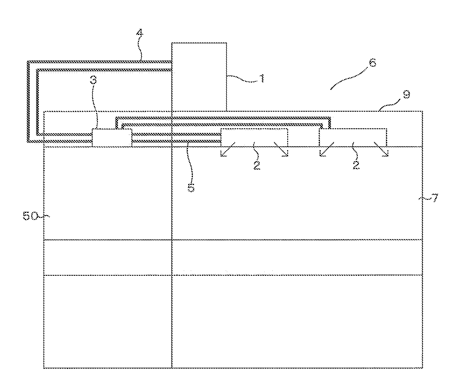
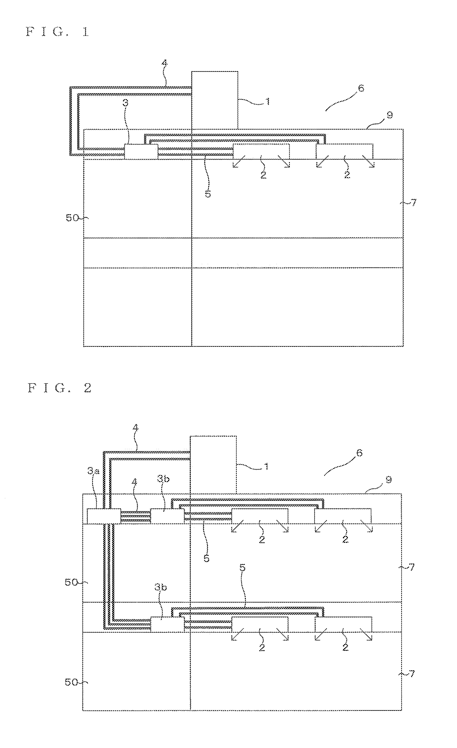
[0027]FIGS. 1 and 2 are each entire configuration diagram illustrating an example of an installed state of an air-conditioning apparatus according to Embodiment 1 of the present invention. On the basis of FIGS. 1 and 2, a configuration of the air-conditioning apparatus will be described. This air-conditioning apparatus performs a cooling operation or a heating operation using refrigeration cycles (a refrigeration cycle and a heat-medium circulation circuit) through which refrigerants (a heat-source side refrigerant and a heat medium (water, anti-freezing fluid and the like)) is circulated. In the following drawings including FIG. 1, the relationship among the sizes of constituent members might be different from the actual one.

[0028]As shown in FIG. 1, this air-conditioning apparatus has a single heat-source device 1 as a heat-source machine, a plurality of indoor units 2, and a relay unit 3 located between the heat-source device 1 and the indoor units 2. The relay unit 3 exchanges h...

embodiment 2

[0144]In Embodiment 1, the heat-medium leakage from the heat-medium circulation circuit for heating and the heat-medium leakage from the heat-medium circulation circuit for cooling are detected in one process (FIG. 8). This is not limiting, and the heat-medium leakage from the heat-medium circulation circuit for heating and the heat-medium leakage from the heat-medium circulation circuit for cooling may be detected in separate processes. In Embodiment 2, the items not particularly described are assumed to be the same as those in Embodiment 1, and the same functions and configurations are described using the same reference numerals.

[0145]FIGS. 9 and 10 are flowcharts illustrating an example of a leakage detecting method of a heat medium according to Embodiment 2 of the present invention. FIG. 9 is a flowchart illustrating a detecting method of heat leakage from the heat source circulation circuit for heating. FIG. 10 is a flowchart illustrating a detecting method of heat leakage from...

embodiment 3

[0159]In Embodiment 1 and Embodiment 2, the leakage of the heat medium from the heat-medium circulation circuit is detected on the basis of the temperature of the heat medium circulating through the heat-medium circulation circuit. This is not limiting, and the leakage of the neat medium from the heat-medium circulation circuit is detected on the basis of a current value of the pump 21. In Embodiment 3, the items not particularly described are assumed to be the same as those in Embodiment 1 or Embodiment 2, and the same functions and configurations are described using the same reference numerals.

[0160]FIG. 11 is an outline circuit diagram illustrating a configuration of an air-conditioning apparatus according to Embodiment 3 of the present invention. As shown in FIG. 11, in the first pump 21a disposed in the heat-medium circulation circuit for heating, a current detection portion 75a that detects a current flowing through this first pump 21a (more specifically, a motor of the first ...


PUM

PropertyMeasurementUnit
temperatureaaaaaaaaaa
energyaaaaaaaaaa
sizesaaaaaaaaaa

Abstract

An air-conditioning apparatus has at least one intermediate heat exchanger that exchanges heat between a refrigerant changing in two phases or a refrigerant in a supercritical state and a heat medium such as water and anti-freezing fluid different from the refrigerant, a refrigeration cycle in which a compressor, a heat-source side heat exchanger, at least one expansion valve, and a refrigerant-side channel of the intermediate heat exchanger are connected via a pipeline through which the refrigerant flows, and a heat-medium circulation circuit in which a heat-medium side channel of the intermediate heat exchanger, a pump, and a use-side heat exchanger are connected via a pipeline through which the heat medium flows, in which in the heat-medium circulation circuit, a fourth temperature sensor that detects a temperature of the heat-medium flowing out of the use-side heat exchanger is provided, and leakage of the heat medium from the heat-medium circulation circuit is detected on the basis of a change amount of a detected temperature of the fourth temperature sensor.

Description

TECHNICAL FIELD[0001]The present invention relates to an air-conditioning apparatus applied to a multiple-unit air conditioner for a building and the like.BACKGROUND ART[0002]Hitherto, a multi air conditioner for a building to which an air-conditioning apparatus that performs a cooling operation or a heating operation by circulating a refrigerant between an outdoor unit, which is a heat source machine arranged outside a room, and an indoor unit arranged inside the room so as to convey cooling energy or heating energy to a region to be air-conditioned such as an indoor space is applied has been present. As the refrigerant used in such an air-conditioning apparatus, HFC refrigerants, for example, are widely used. Also, a natural refrigerant such as carbon dioxide (CO2) has begun to be used.[0003]Also, an air-conditioning apparatus of other configurations represented by a chiller system is present. In this air-conditioning apparatus, cooling energy or heating energy is generated in a h...

Claims


Application Information

Patent Timeline
Patent Type & Authority Applications(United States)
IPC IPC(8): G01K13/00
CPCF25B13/00Y02B30/12F25B49/005F25B2309/061F25B2313/0272F25B2313/02741F25B2500/222F24D3/18F24D2200/123F24D2220/0207F24D2220/0235F24D2220/042F24D2220/06F24F2011/0084F25B2500/221F25B2700/21F24D19/1039F25B25/005F25B2313/0231F24F11/36
Inventor TAKATA, SHIGEO
Owner MITSUBISHI ELECTRIC CORP
Why Eureka
Try Eureka