Automotive Brake Light with Graduated Display

a technology of brake light and graduated display, which is applied in the direction of signalling/lighting devices, vehicle components, emergency signal devices, etc., can solve the problems of affecting the relationship between brake pressure and actual deceleration, not being able to reliably indicate actual vehicle deceleration, and relatively low deceleration rate on gravel

Active Publication Date: 2011-12-15
KISIEL ANTHONY J
View PDF19 Cites 15 Cited by
  • Summary
  • Abstract
  • Description
  • Claims
  • Application Information

AI Technical Summary

Benefits of technology

[0005]In a preferred form, the brake light assemblies include plastic or glass lenses inside of which are mounted a plurality of LEDs. This implementation has the advantage of substantially instant illumination as opposed to conventional incandescent filament lights, which exhibit a significant delay between the application of current and the production of visible illumination. However, filament and gas discharge or halogen lights can be used with the present invention.

Problems solved by technology

This system suffers a number of disadvantages, including variability of actual deceleration display from vehicle to vehicle in the field, and the fact that brake application level, whether represented by pedal displacement or brake line pressure, is not a reliable indicator of actual vehicle deceleration.
Furthermore, the quality of the road surface, tire composition and condition, all affect deceleration and even hard brake application may produce a relatively low deceleration rate on gravel, or wet and / or snow or ice-covered surfaces.
If a vehicle is equipped with a regenerative brake energy capture system or a Jake / Exhaust / Retarder system, this may affect the relationship between brake pressure and actual deceleration.

Method used


Image

  • Automotive Brake Light with Graduated Display
  • Automotive Brake Light with Graduated Display
  • Automotive Brake Light with Graduated Display

Examples


Embodiment Construction

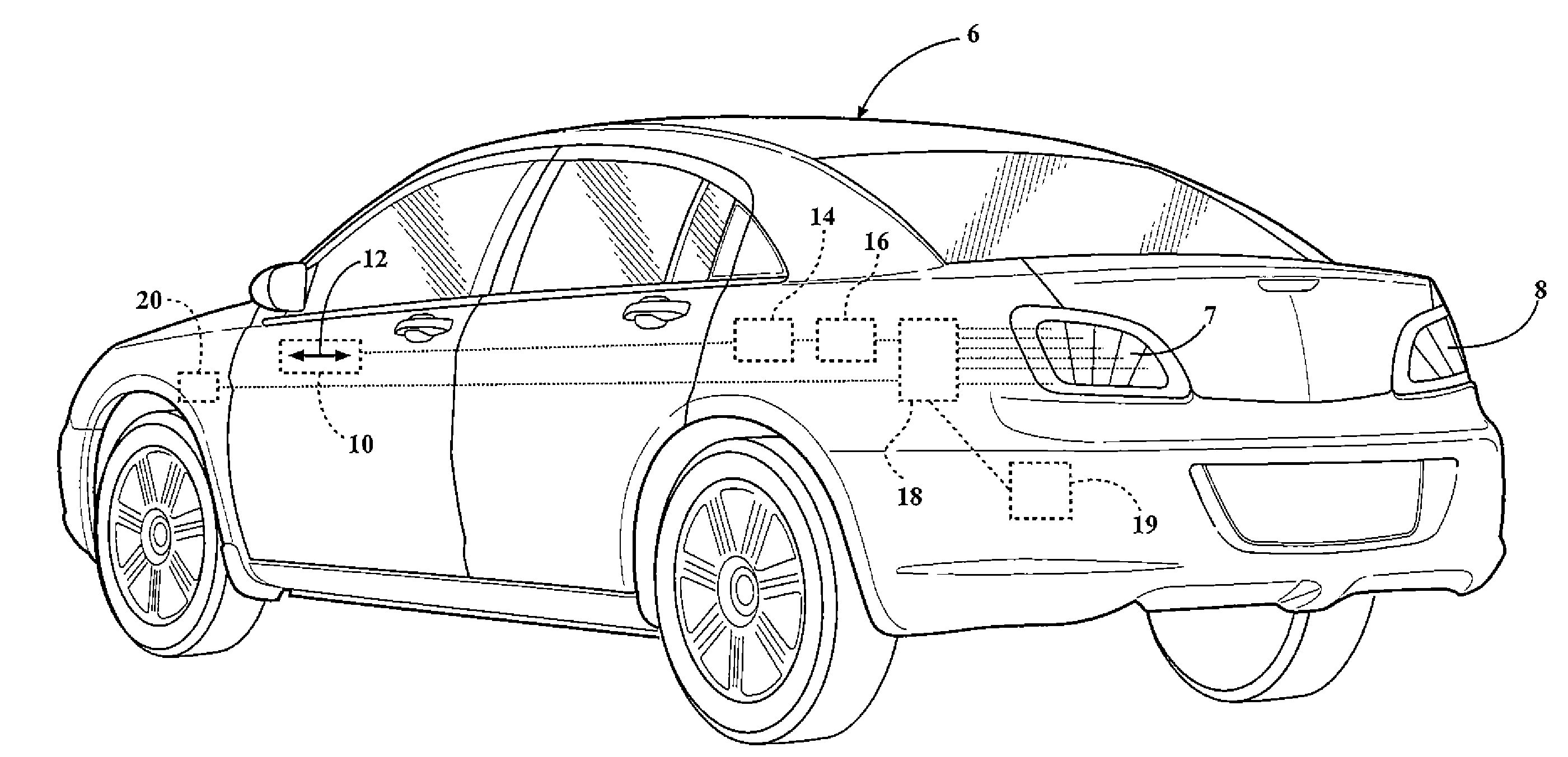
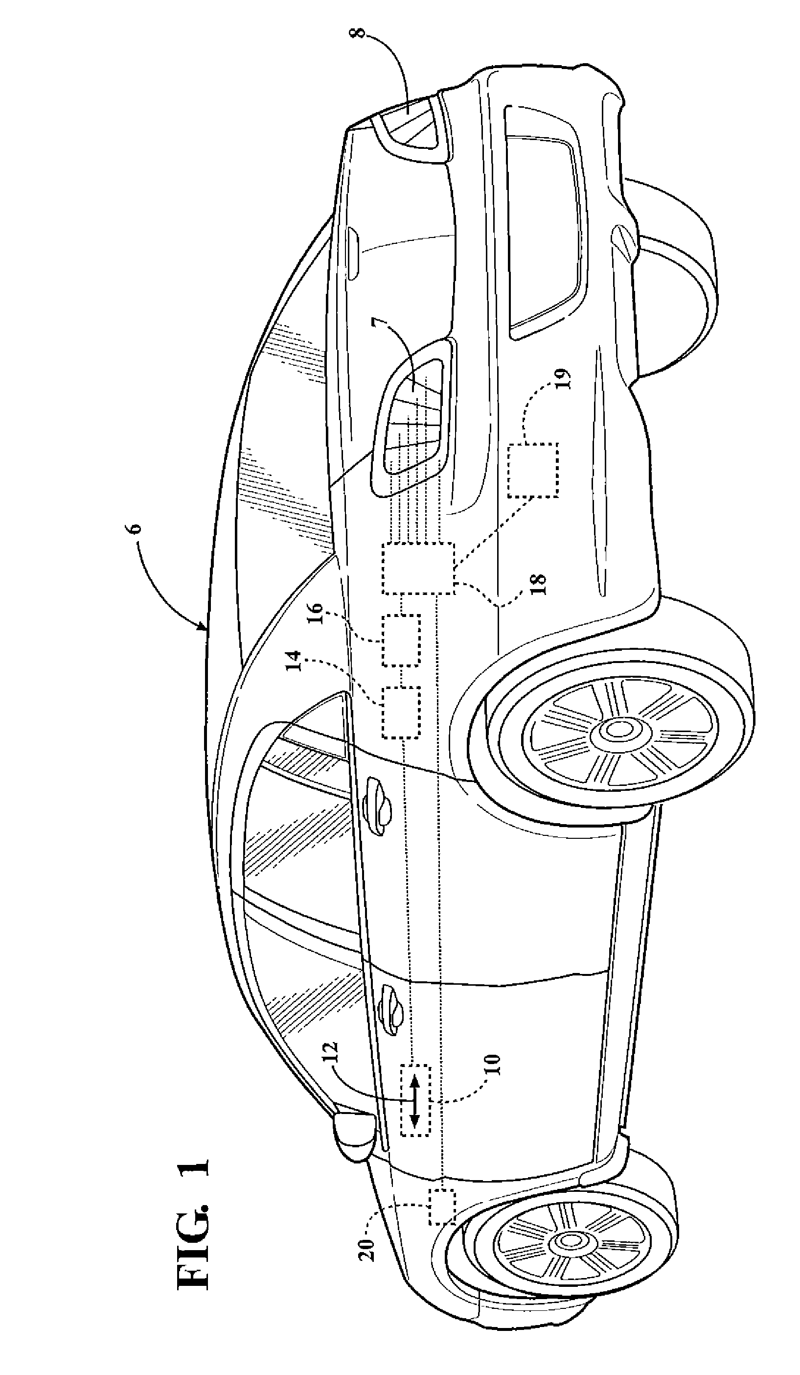
[0013]Referring to FIGS. 1 and 4, there is shown a vehicle 6 equipped with rear-mounted, spaced-apart lights 7, 8. The vehicle 6 carries an accelerometer 10 mounted in the vehicle in such a fashion that the sensitive axis of the accelerometer 12 corresponds to the longitudinal axis of the vehicle. The accelerometer is preferably a piezoelectric single axis accelerometer having a range of about 0.02 g to about 2.0 g and producing a proportional output signal which is connected to an interface 14 which converts the output signal by digitization and / or power level switching as necessary to provide a compatible input to a controller 16 such as a microprocessor or microchip in which a lighting program is stored. Suitable accelerometers are available from Freescale Semiconductor, Inc. The term “stored” embraces both or all of (1) hard-wiring with, for example, solid state relay-type devices or switches, (2) software programming, and (3) integrated circuitry available from a variety of man...


PUM


Abstract

An automotive brake light system producing a graduated display according to the level of vehicle deceleration as sensed by an onboard piezoelectric accelerometer. Taillight assemblies are divided into segments which are illuminated in sequence to produce a graduated display. The vehicle anti-lock brake system may be connected into the system to provide a special lighting effect such as blinking the taillights during a panic stop condition.

Description

SUMMARY OF THE INVENTION[0001]This invention relates to rear-mounted automotive brake light systems and more particularly to a system in which the brake light or lights are illuminated in a graduated fashion to represent and convey information to other drivers regarding different degrees of deceleration of the vehicle.BACKGROUND OF THE INVENTION[0002]Conventional automotive braking systems are essentially binary in nature; i.e., the lights are illuminated when the brakes are applied and are not illuminated when the brakes are not applied.[0003]U.S. Patent Publication No. 2010 / 0085180 describes a brake light system using a potentiometer to sense pedal travel or brake application pressure and to produce a signal illuminating a brake light assembly in a graduated fashion thereby to convey information to a following vehicle driver regarding the driver-initiated braking action of the lead vehicle. This system suffers a number of disadvantages, including variability of actual deceleration...

Claims


Application Information

Patent Timeline
Patent Type & Authority Applications(United States)
IPC IPC(8): B60Q1/44
CPCB60Q1/448B60Q1/444
Inventor KISIEL, ANTHONY J.
Owner KISIEL ANTHONY J
Why Eureka
Try Eureka