Apparatus For Electric Power Distribution

a technology for electric power distribution and apparatus, applied in the direction of substation/switching arrangement details, shutters/guards preventing contact access, substation/switching arrangement boards/panels/desks, etc., can solve problems such as troublesome maintenance work, and achieve the effect of facilitating maintenance work, low weight and non-expensiv

Active Publication Date: 2011-12-15
ABB (SCHWEIZ) AG
View PDF6 Cites 7 Cited by
  • Summary
  • Abstract
  • Description
  • Claims
  • Application Information

AI Technical Summary

Benefits of technology

[0017]The inventors of the present invention have identified the request for more compact electrical equipment enclosures, especially more compact metering panels, in order to take up less space when installed on site. A way to make e.g. a metering panel more compact, is to place the equipment of separate phases of electricity closer to one another. To reduce the distances between the phases of electricity within the enclosure without increasing the risk of arc faults, flash-over or electrical discharges between the phases of electricity, the inventors found the use of electrically insulating barriers between the phases of electricity to be advantageous. However, the inventors found that such barriers may prevent the access to electrical components during maintenance work, even if they would be movable, and when being movable, such barriers may be difficult to move or remove during maintenance work, resulting in a troublesome maintenance work.
[0045]According to another advantageous embodiment of the metering panel according to the present invention, where the apparatus has an enclosure having two opposite side walls, for each phase of electricity a Voltage Transformer is mounted to one of the side walls and within the enclosure, and a Current Transformer is mounted to the opposite side wall and within the enclosure. By the innovative barrier and / or outer panel of the present invention, flexibility is attained with regard to the entry of conductors, e.g. cables or busbars, and the mounting of the Voltage Transformers and Current Transformers. A conductor entering the enclosure to be connected to the Current Transformer may enter the enclosure from below or via any of the two opposite side walls, and the Current Transformer may be mounted to any of the side walls and the Voltage Transformer to the other. According to a further advantageous embodiment of the metering panel according to the present invention, for each phase of electricity the electrical component is located somewhere between the Voltage Transformer and the Current Transformer.

Problems solved by technology

However, the inventors found that such barriers may prevent the access to electrical components during maintenance work, even if they would be movable, and when being movable, such barriers may be difficult to move or remove during maintenance work, resulting in a troublesome maintenance work.

Method used


Image

  • Apparatus For Electric Power Distribution
  • Apparatus For Electric Power Distribution
  • Apparatus For Electric Power Distribution

Examples


Embodiment Construction

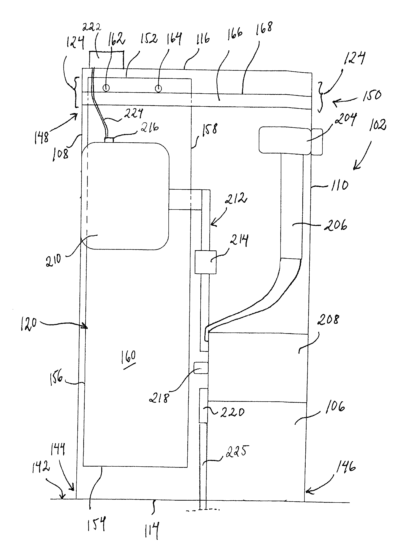
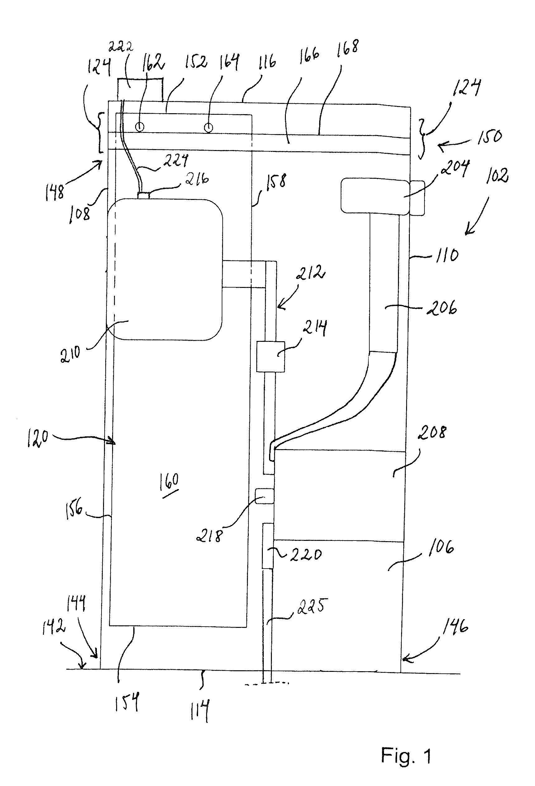
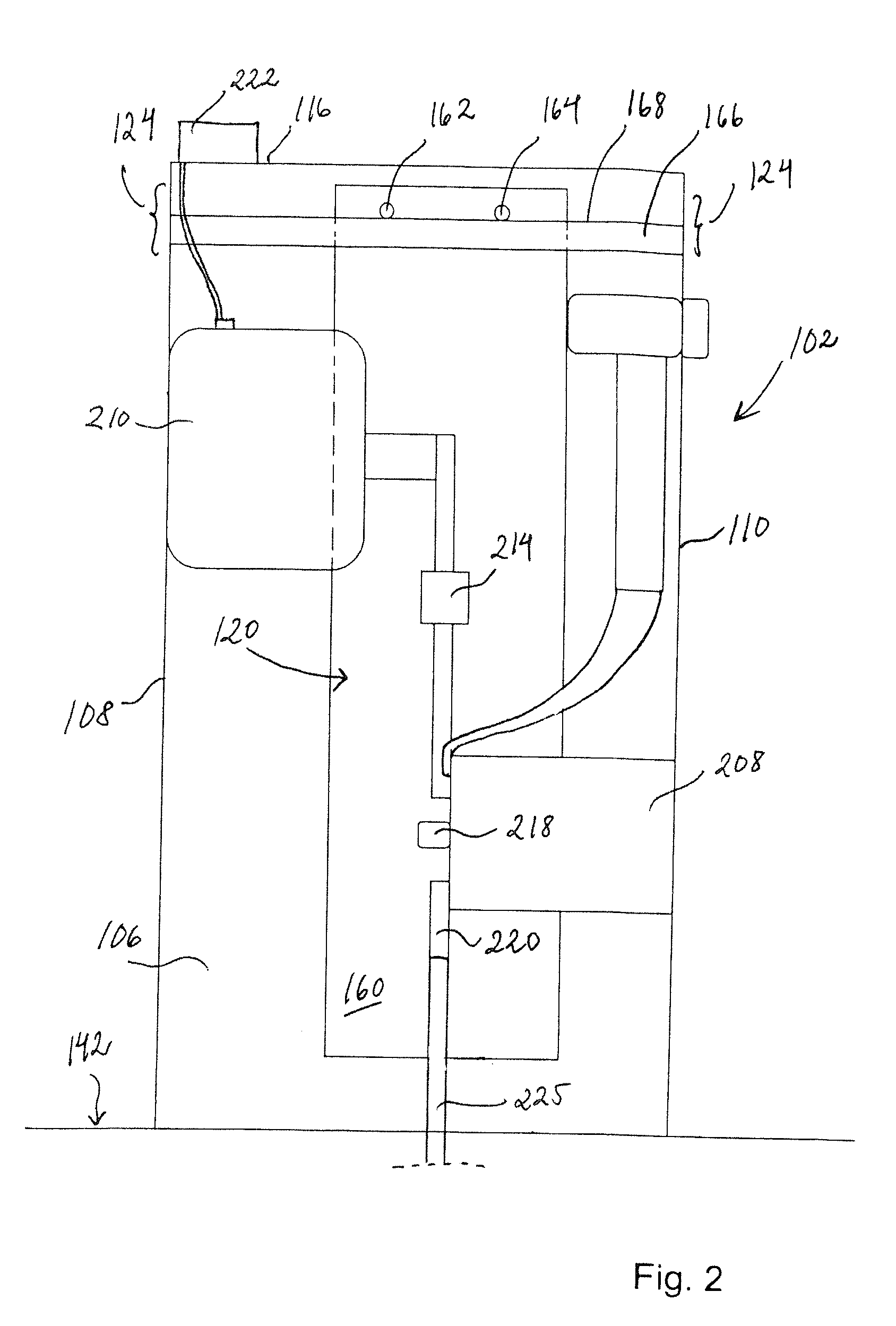
[0059]FIGS. 1-4 shows schematically an embodiment of the metering panel connectable to an electric power distribution system according to the present invention, the metering panel comprising an embodiment of the apparatus according to the present invention, both adapted for medium and / or high voltage, e.g. 1 kV and above. The metering panel / apparatus comprising an enclosure 102 which has an access opening 104 (see FIG. 3) and defines an interior space 106. The enclosure 102 may be in the form of a cabinet. The enclosure 102 shown comprises a first side wall 108 and a second side wall 110 opposite one another and connected via a third side wall 112. The enclosure 102 further comprises a base 114 and a top wall 116. The base 114 may be in the form of a hollow frame or a solid section. The top wall 116 may also be replaced by a hollow frame, but a top wall is advantageous to protect the interior space 106 of the enclosure 102 from e.g. dust. The first and second side walls 108, 110, th...


PUM


Abstract

An apparatus, such as a metering panel, for electric power distribution. An enclosure having an access opening defining an interior space, at least two electrical components for separate phases of electricity. The two components located within the enclosure and spaced laterally apart, at least one electrically insulating barrier panel, movable between at least two guided positions, a working position within the enclosure and between the components and an access position displaced from the components.

Description

CROSS-REFERENCE TO RELATED APPLICATIONS[0001]The present application claims priority of European patent application No. 10165580.1 filed on Jun. 10, 2010, the content of which is incorporated herein by reference.FIELD OF THE INVENTION[0002]The present invention relates to an apparatus for electric power distribution, comprising an enclosure having an access opening and defining an interior space, at least two electrical components for separate phases of electricity within the apparatus, the two components being located within the enclosure and being spaced laterally from one another, at least one barrier panel formed of an electrically insulating material, the barrier panel being movable in relation to the enclosure between at least two positions, and guiding means for guiding the barrier panel between the at least two positions. The guiding means are adapted to guide the barrier panel to a working position in which the barrier panel is located within the enclosure and between the c...

Claims


Application Information

Patent Timeline
Patent Type & Authority Applications(United States)
IPC IPC(8): H02B1/26
CPCH02B1/14
Inventor LUNDEN, ARNSTEINJACOBSEN, FRODE-WILLYSONSTEBY, GUNN KRISTINTVETEN, JOHN-ANDERSWEST, JOHN RUNESANDVIK, LILL-BENTENAPER, OIVINDSKRYTEN, PAAL KRISTIANLAURITZEN, RICHARDENDRE, THOR
Owner ABB (SCHWEIZ) AG
Why Eureka
Try Eureka