Supercharge Your Innovation With Domain-Expert AI Agents!

Composite thermal insulation material

a technology of thermal insulation materials and composite materials, applied in the direction of insulation improvement, building components, applications, etc., can solve the problems of many relatively low thermal insulation materials that are weak and unsuitable, and the advantage of a relatively high thermal conductivity

Inactive Publication Date: 2011-12-15
MICROTHERM
View PDF1 Cites 10 Cited by
  • Summary
  • Abstract
  • Description
  • Claims
  • Application Information

AI Technical Summary

Benefits of technology

[0009]The casing may be formed of a number of components secured together to define a chamber for the core. The casing may be formed of two substantially identical components.
[0010]The casing components may be secured together with an adhesive. The adhesive may be selected from a bituminous adhesive, an epoxy adhesive, a butyl rubber adhesive, a contact adhesive, a polyurethane adhesive, an acrylic adhesive, a hot melt adhesive and a silyl modified adhesive.
[0011]Alternatively or additionally, the casing components may be secured together by mechanical means.
[0012]Alternatively, the l

Problems solved by technology

However, it has the disadvantage of a relatively high thermal conductivity at about 0.038 to about 0.05 W / mK.
Many relatively low thermal conductivity insulation materials are weak and unsuitable where rigidity and strength are required.
Glass sheets, though, have the disadvantage that they do not have significant strength unless manufactured using special processes, such as lamination, which increase the cost of the casing.

Method used


Image

  • Composite thermal insulation material
  • Composite thermal insulation material
  • Composite thermal insulation material

Examples


example 1

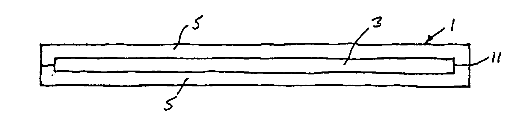
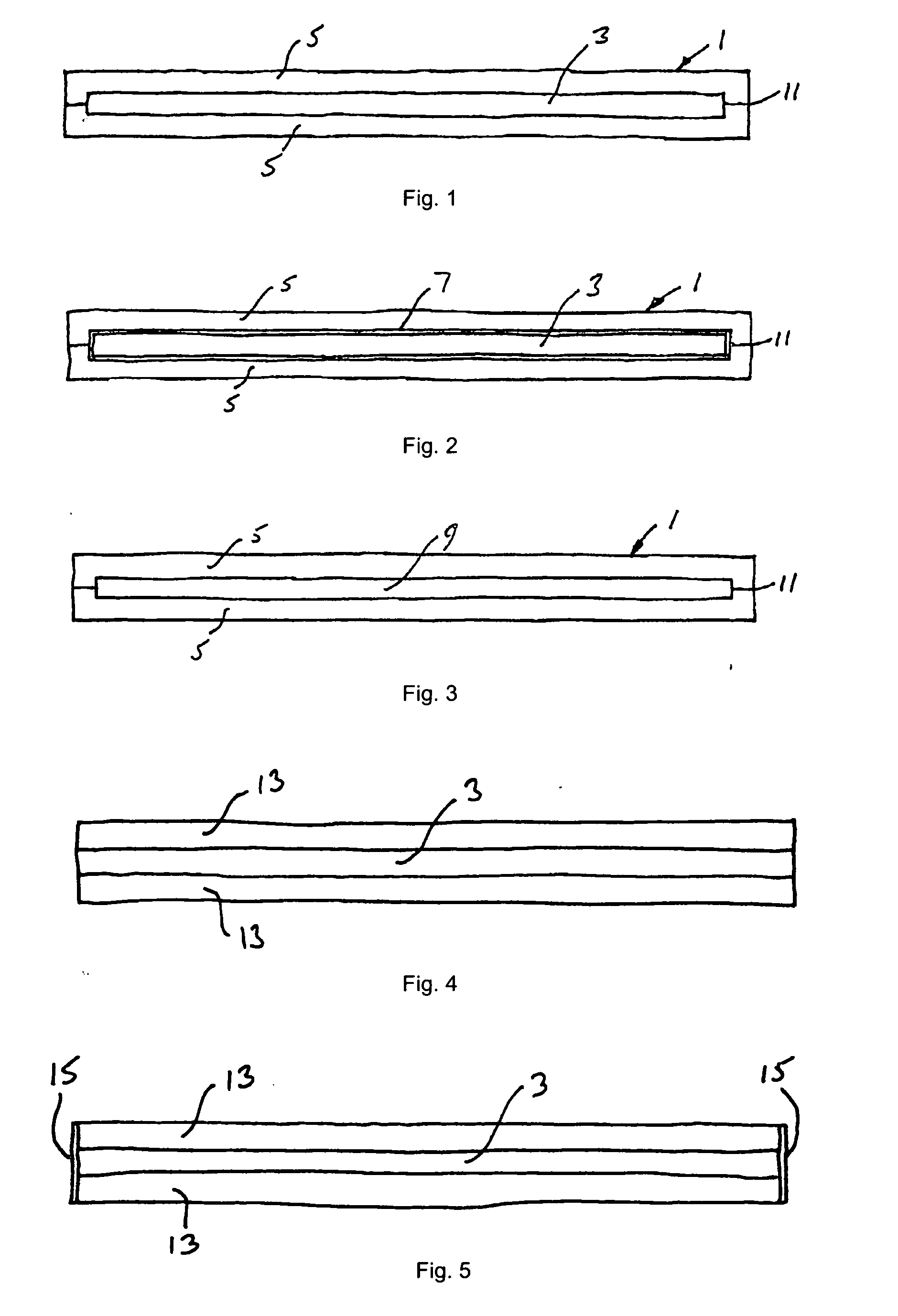
[0040]A composite thermal insulation panel was made by preparing two casing parts of FOAMGLAS cellular glass material from Pittsburgh Corning Europe, each casing part having external dimensions of 739 mm by 490 mm by 39 mm and a density of 160 kg / m3. Each casing part was formed with a recess having dimensions of 703 mm by 452 mm and a depth of 10 mm. An evacuated panel of SLIMVAC from Microtherm Europe having dimensions of 700 mm by 450 mm by 18 mm was placed in the chamber formed by the two recesses and the two casing parts were secured together with a bituminous adhesive to provide 30 mm of cellular glass material on each side of the panel.

[0041]The original cellular glass material had a thermal conductivity of 0.042 W / mK, while the evacuated panel had a thermal conductivity of less than 0.005 W / mK and the composite thermal insulation panel was tested to determine a thermal conductivity of 0.0167 W / mK at 10 degrees Celsius, giving a substantial improvement over the thermal conduct...

example 2

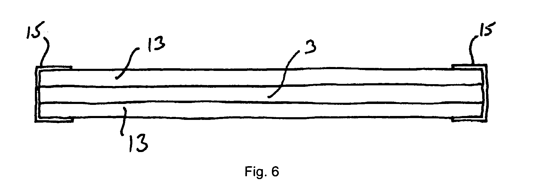
[0042]A composite thermal insulation panel was made by preparing two casing parts of FOAMGLAS cellular glass material as in Example 1. A panel of compacted microporous thermal insulation material having the composition, in percent by weight, amorphous silica 90, silicon carbide 5 and PET filaments 5 was placed in the chamber formed by the two recesses and the two casing parts were secured together with a bituminous adhesive to provide 30 mm of cellular glass material on each side of the panel as in Example 1. The resulting composite thermal insulation material was not evacuated.

[0043]The composite thermal insulation panel was found to have a thermal conductivity of 0.0347 W / mK at 10 degrees Celsius, again giving a significant improvement over the thermal conductivity of the original . cellular glass. It is believed that the thermal conductivity of such a composite thermal insulation panel would fall to substantially that of Example 1 if the chamber is evacuated.


PUM

PropertyMeasurementUnit
Adhesivityaaaaaaaaaa
Mechanical propertiesaaaaaaaaaa
Thermal propertiesaaaaaaaaaa

Abstract

A composite thermal insulating material comprises a layer (3, 9) of thermal insulating material between two layers (5, 13) of material selected from cellular glass and cellular concrete material.

Description

TECHNICAL FIELD[0001]This invention relates to a composite thermal insulation material which may be used, for example in building applications.BACKGROUND ART[0002]Cellular glass insulation is a lightweight, rigid material composed of a large number of small, sealed glass cells. Cellular glass has the advantages of being water impermeable and resistant to moisture, it is incombustible, resistant to corrosion, it is dimensionally stable, i.e., rigid, and has high compressive strength. Cellular glass insulation therefore has many uses including the insulation of flat roofs, standing seam roofs, green roofs, car park decks, interior, exterior and cavity walls, and under and over concrete and hardcore floors. However, it has the disadvantage of a relatively high thermal conductivity at about 0.038 to about 0.05 W / mK. Cellular concrete is a similar, lightweight rigid material composed of a large number of small, sealed cells.[0003]Many relatively low thermal conductivity insulation materi...

Claims


Application Information

Patent Timeline
IPC IPC(8): B32B3/12
CPCC04B28/02Y10T428/24149C04B2103/56C04B2111/00612E04B1/80E04B1/803E04B2001/742Y02B80/12C04B30/02E04C2/296E04C2/2885C04B14/062C04B14/303C04B14/42C04B14/4631C04B16/06C04B14/022C04B14/30C04B14/305C04B14/308C04B14/324C04B38/00Y02B80/10Y02A30/242E04C2/26E04C2/288
Inventor HEYTENS, STEVENVAN GUCHT, BAUDEWIJN
Owner MICROTHERM
Features
  • R&D
  • Intellectual Property
  • Life Sciences
  • Materials
  • Tech Scout
  • Unparalleled Data Quality
  • Higher Quality Content
  • 60% Fewer Hallucinations
Learn More