Thermal Anemometer Flow Meter for The Measurement of Wet Gas Flow

a flow meter and gas flow technology, which is applied in the direction of liquid/fluent solid measurement, volume metering, instruments, etc., can solve the problems of 20% error in gas flow measurement, complicated design involving multiple pressure transducers, and difficult measurement of gas flows containing liquid droplets or mists

Active Publication Date: 2011-12-22
LOS ROBLES ADVERTISING
View PDF17 Cites 28 Cited by
  • Summary
  • Abstract
  • Description
  • Claims
  • Application Information

AI Technical Summary

Problems solved by technology

The measurement of gas flows containing liquid droplets or mist is known to be very difficult.
For example, Steven and Hall published data showing that for an orifice plate differential pressure flow meter, a 10% liquid mass flow leads to a 20% error in gas flow measurement.
Daniel and Lund describe a technique to measure wet gas flow rate using a venturi differential pressure type device however the design is very complicated involving multiple pressure transducers.
An additional disadvantage of these differential pressure meters is that they have a very narrow dynamic operating range, typically 5:1 or at the most 10:1.
Such a meter would have to be sized for the high flow and would not have a usable signal during the low flow period.
Ultrasonic and vortex shedding type flow meters have been used to measure wet gas flow but these instruments suffer from disadvantages as well.
Vortex shedding flow meters cannot measure at low flow velocities and ultrasonic meters are expensive and suffer from liquid film effects on the transducers.
However, thermal anemometer type flow meters are very sensitive to liquid in the gas stream since any liquid contacting the sensor probes will cause a high erroneous reading.

Method used


Image

  • Thermal Anemometer Flow Meter for The Measurement of Wet Gas Flow
  • Thermal Anemometer Flow Meter for The Measurement of Wet Gas Flow
  • Thermal Anemometer Flow Meter for The Measurement of Wet Gas Flow

Examples


Embodiment Construction

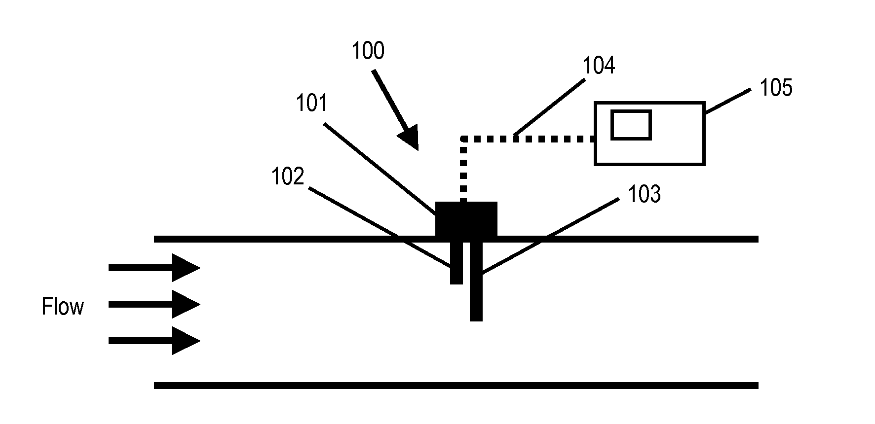
[0034]FIG. 1 illustrates a conventional thermal anemometer flow meter 100. Flow meter 100 includes a thermal anemometer sensor 101 having probes 102 and 103, leads 104, and an electric controller circuit 105. Probes 102 and 103 are inserted into a stream. Probe 102 measures the stream temperature while probe 103 is heated and simultaneously monitors its own temperature. Leads 104 connect probes 102 and 103 to an electrical controller circuit 105 to form a thermal anemometer flow meter. While there are several modes by which flow meter 100 can operate, in one mode electrical controller circuit 105 provides electrical power input to probe 103 to maintain its temperature at a set value above the temperature sensed by probe 102 (i.e., the stream temperature). The power required is a function of heat loss, which is proportional to the mass flow of the stream past probe 103. A variety of commercial flow instrumentation is produced and sold using this technology. Several important aspects ...


PUM


Abstract

A flow body flow meter includes a flow body and a sensor having one or more probes in the flow body. As a wet gas stream enters the flow body, an internal passage imparts angular momentum to the stream to induce a rotating flow. The wet gas stream at least intermittently carries liquid phase particles and the inertia of the denser liquid phase particles separates them from the rotating flow. The probes of the sensor are located in a part of the rotating flow that is free of any liquid phase particles. The internal passage may include an axial swirler and a cylindrical section downstream from the axial swirler. The axial swirler imparts the nonlinear motion to the stream, and tips of the probes are located near a center axis of the cylindrical section so they are free of any liquid phase particles.

Description

FIELD OF INVENTION[0001]This invention relates to methods and apparatus to measure flow characteristics of a stream of gas phase particles that intermittently carries liquid phase particles.DESCRIPTION OF RELATED ART[0002]The measurement of gas flows containing liquid droplets or mist is known to be very difficult. For example, Steven and Hall published data showing that for an orifice plate differential pressure flow meter, a 10% liquid mass flow leads to a 20% error in gas flow measurement. See R. Steven, A. Hall, Flow Measurement and Instrumentation 20(2009) 141-151. While they show a correlation that allows the meter to be corrected to provide a reading within 2% of the actual gas flow, this requires knowing the liquid mass flow rate. Similar errors were reported by Lupeau and co-workers for a venturi differential pressure flow meter. See A. Lupeau et al., Flow Measurement and Instrumentation 18(2007)1-11. Other flow meter types have been applied to the measurement of so called ...

Claims


Application Information

Patent Timeline
Patent Type & Authority Applications(United States)
IPC IPC(8): G01P5/10
CPCG01F1/6842
Inventor DALLA BETTA, RALPH A.KURZ, DANIEL R.BURTON, BRUCE B.MARTINEZ, RICARDOKURZ, JEROME L.
Owner LOS ROBLES ADVERTISING
Why Eureka
Try Eureka