Force transfer assembly

Inactive Publication Date: 2011-12-22
SCHLUCKEBIER FLOYD A
View PDF18 Cites 10 Cited by
  • Summary
  • Abstract
  • Description
  • Claims
  • Application Information

AI Technical Summary

Benefits of technology

[0009]The advantages of the force transfer assembly described herein include relatively low friction, low hysteresis, a simple mounting structure relative to what is required for bell cranks, walking beams, or other similar devices, small radii for force transmittal relative to that possible with a Bowden cab

Problems solved by technology

The structure of conventional motion transfer assemblies, comprised of various mechanical linkages, pulleys, and cranks, for example, is often complicated and requires complex tooling to manufacture.
Additionally, conventional motion transfer as

Method used


Image

  • Force transfer assembly
  • Force transfer assembly
  • Force transfer assembly

Examples


Example

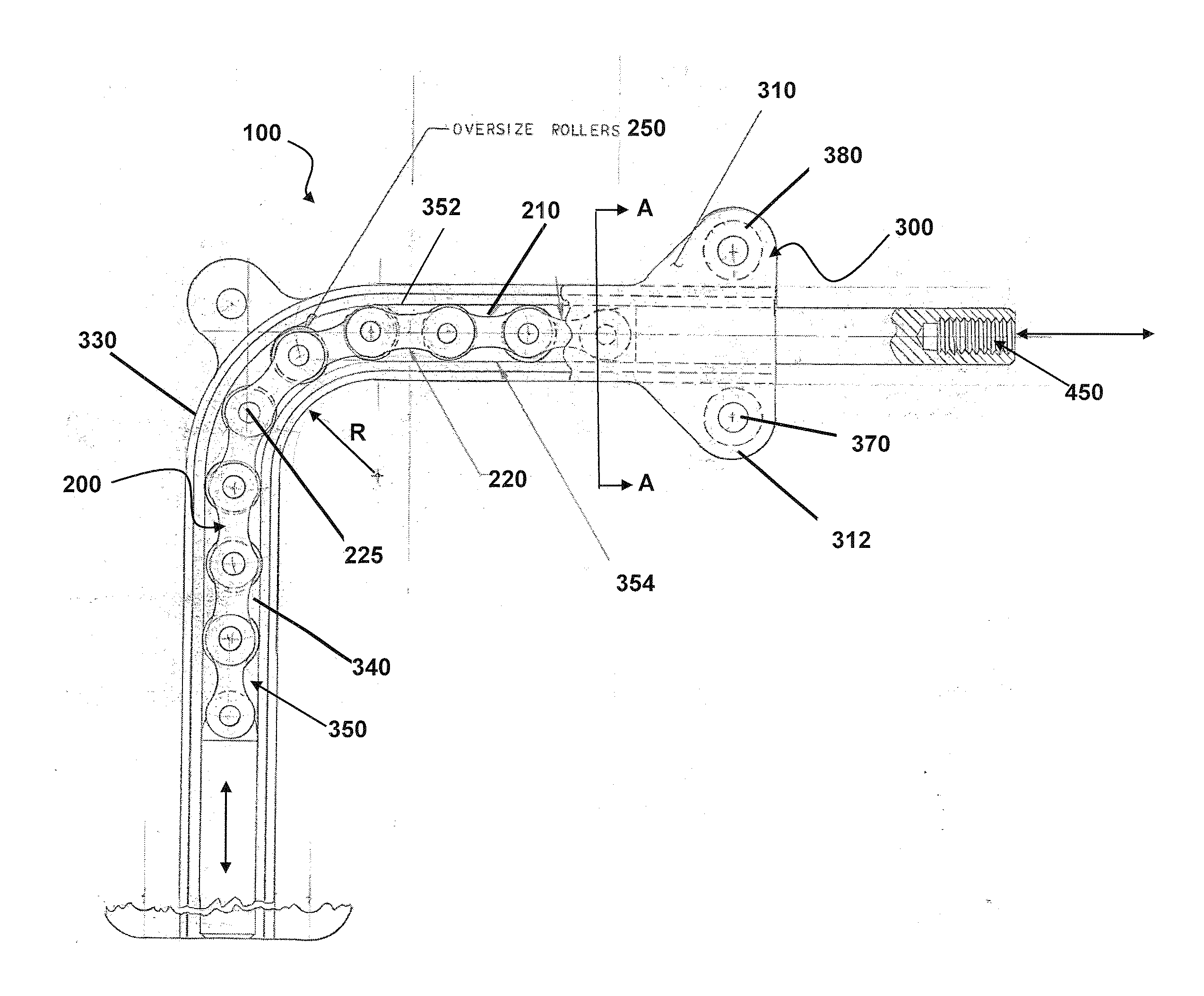
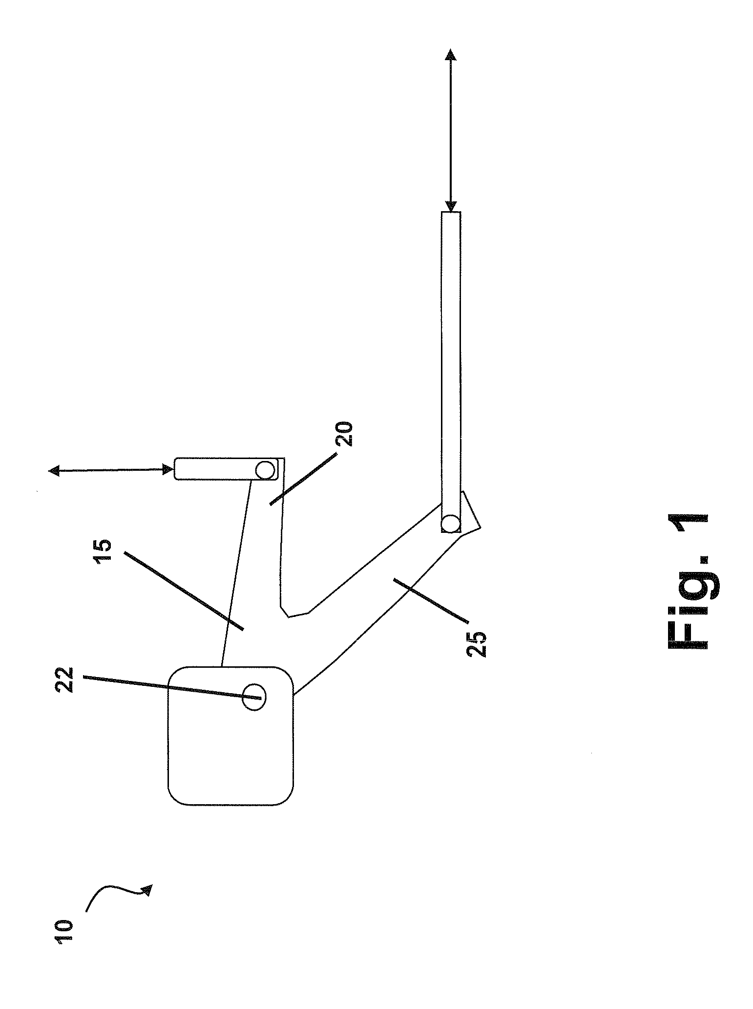
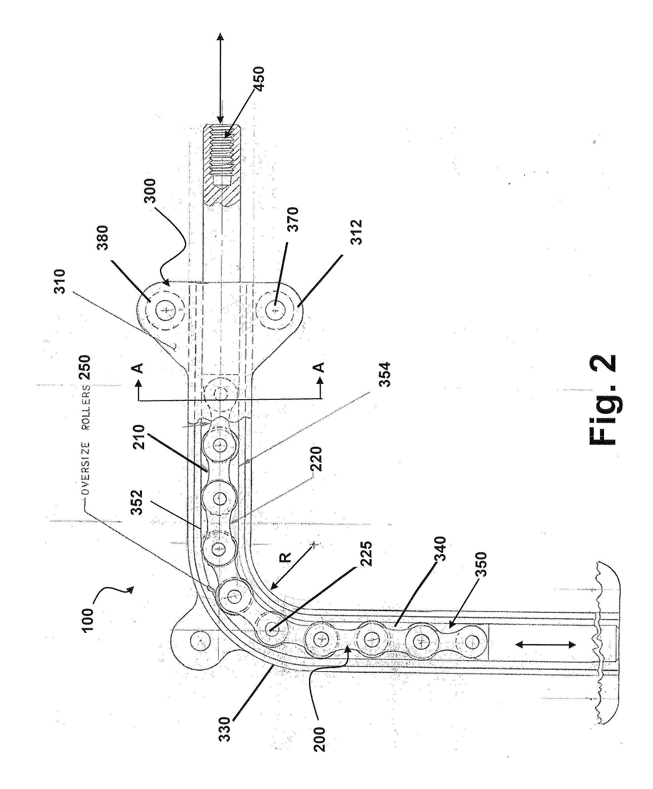
[0017]The present invention is described more fully hereinafter with reference to the accompanying drawings, in which various aspects of a force transfer assembly are shown. This invention, however, may be embodied in many different forms and should not be construed as limited by the various aspects of the force transfer assembly presented herein. The detailed description of the force transfer assembly is provided below so that this disclosure will be thorough and complete, and will fully convey the scope of the present invention to those skilled in the art.

[0018]The detailed description may include specific details for illustrating various aspects of a force transfer assembly. However, it will be apparent to those skilled in the art that the invention may be practiced without these specific details.

[0019]Various aspects of a force transfer assembly may be illustrated by describing components that are coupled together. As used herein, the term “coupled” is used to indicate either a ...


PUM


Abstract

A force transfer assembly that can transfer force at various angles and through relatively small bend radii includes a roller chain constrained in a raceway channel. The configuration provides multi-dimensional support so that a roller chain assembly, typically constrained to tensile loading, may also be used for compressive loading. A method for transmitting force along a non-linear path includes configuring a raceway channel having an upper raceway surface and a lower raceway surface, securing a chain assembly into the raceway channel between the upper raceway surface and the lower raceway surface with at least one lateral securing mechanism, and applying a tensile or compressive force to one end of the chain assembly in order to have the chain assembly transfer the tensile or compressive force to the other end of the chain assembly.

Description

CROSS-REFERENCE TO RELATED APPLICATIONS[0001]This application claims the priority of U.S. Provisional Patent Application No. 61 / 357,387, filed Jun. 22, 2010, the entire specification, claims and drawings of which are incorporated herein by reference.BACKGROUND[0002]1. Field[0003]Aspects of the present invention relate to a force transfer assembly, and, in particular, to an assembly that effectively transmits loads through various angles in order to effectuate motion in a direction different from that of the axis of applied force.[0004]2. Description of the Related Art[0005]Conventional motion transfer assemblies, such as a Bowden cable, a bell crank, and walking beam assemblies, are typically used for mechanically transferring an applied force from one axis to a different axis. These types of motion transfer assemblies are commonly used in many applications, such as, for example, aircraft wing panels and / or horizontal stabilizers to mechanically actuate the flight control surfaces, ...

Claims


Application Information

Patent Timeline
IPC IPC(8): F16H19/02
CPCY10T74/18832F16H19/0645
Inventor SCHLUCKEBIER, FLOYD A.
Owner SCHLUCKEBIER FLOYD A
Why Eureka
Try Eureka