
Portable Creels With Insertable Yarn Trays and Improved Headers and Yarn Handling Methods

a technology of insertable yarn trays and portable creels, which is applied in the direction of weaving, manufacturing tools, and shuttles, can solve the problems of occupying large amounts of manufacturing facility floor space, requiring significant amount of labor to prepare each bobbin, and preparing and using creels to feed tufting machines and beams requires significant amount of labor, so as to reduce the downtime of tufting machines and other apparatuses, reduce the amount of yarn handling, and facilitate handling

Active Publication Date: 2011-12-22
INTERFACE INC
View PDF1 Cites 16 Cited by
  • Summary
  • Abstract
  • Description
  • Claims
  • Application Information

AI Technical Summary

Benefits of technology

[0019]The use of trays of two or more yarn packages in apparatuses and processes providing yarn to tufting machines can reduce tufting machine, creel and other apparatus down time, permit changes in the locations at which particular yarn handling activities occur, significantly reduce the amount of yarn handling required, and facilitate handling and properly locating yarn of different colors. For example, a creel can be used with a first set of trays to feed a tufting machine while another set of trays is loaded with yarn packages. After use of the first set of trays with the tufting machine, the first set of trays can be quickly replaced within the creel with the second set of trays such that use of the creel can resume again. Such a replacement, because there are fewer trays than individual yarn packages, can be accomplished more quickly than in previous yarn-providing processes in which yarn packages were individually removed from and then loaded onto a creel. In addition, the use of trays reduces inventory, the number of operators required, and allows flexibility in how and where the trays can be loaded (e.g., can be loaded by external vendors).
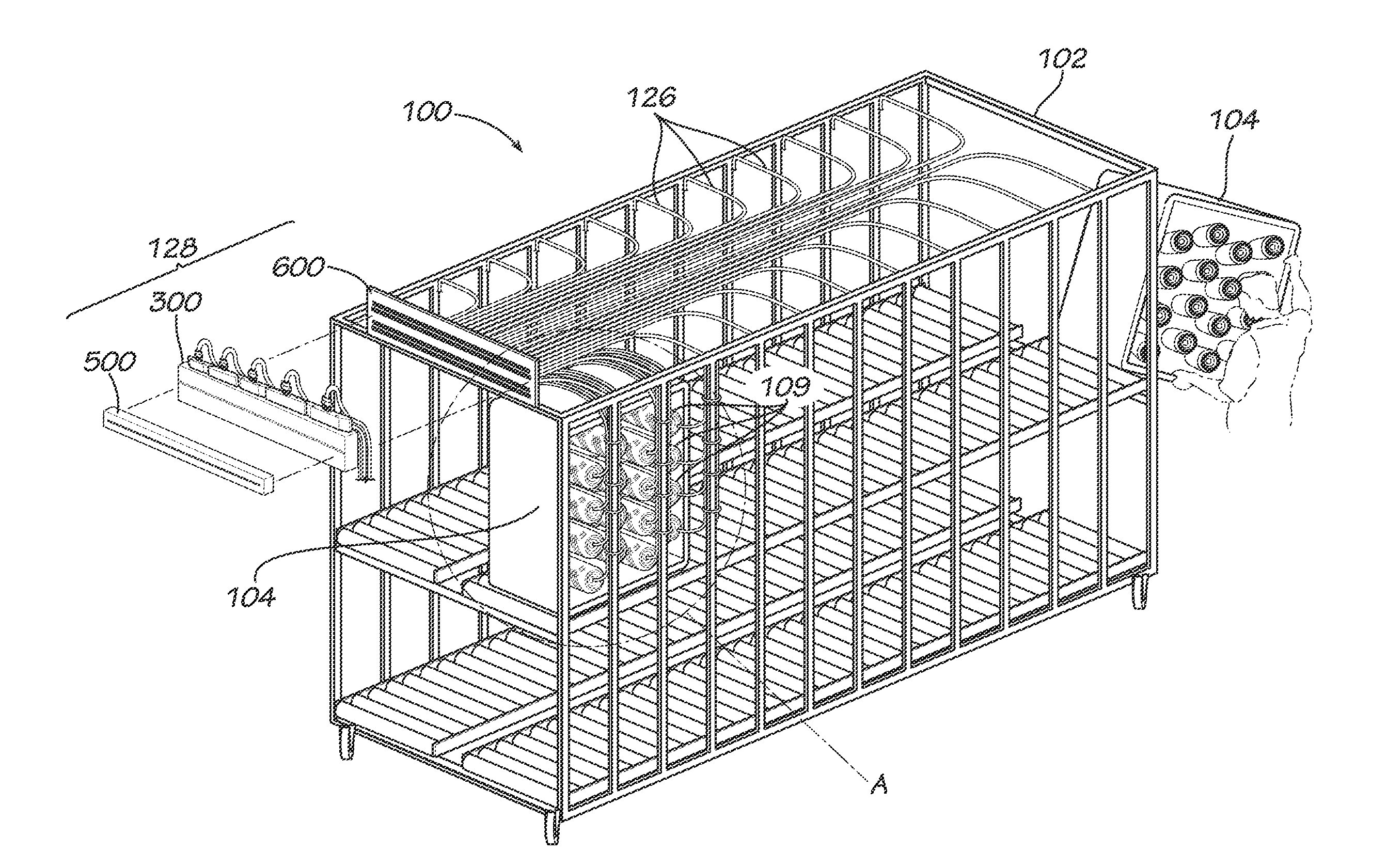
[0020]The configuration and features of a creel facilitate provision of the yarns from the individual yarn packages to the tufting machine. The rack of the creel attaches, supports, or positions trays such that it is feasible and convenient to use the yarns from the individual yarn packages. To facilitate the attachment of individual yarns from the creel to individual yarns already feeding into the tufting machine, which is one technique for initiating use of the creel's yarn by the tufting machine, the creel is configured to automatically or semi-automatically position each of the individual yarns such that the positioned yarns can be more easily attached to those feeding already into the tufting machine. Specifically, the yarns are individually moved along paths from their respective holders to one or more alignment mechanisms, such as a header, on the creel at which the yarns are aligned or otherwise positioned for convenient and efficient attachment to yarns already feeding into the tufting machine.
[0021]To provide such paths for the yarn to be moved without interfering with one another, the rack of the creel comprises tubes preferably extending from positions near the individual yarn packages to positions at one or more alignment mechanisms. The rack is configured so that trays attached to or supported by the rack are positioned such that the individual yarns from their respective yarn packages can be inserted easily and without interfering with one another into individual tube ends during the creel loading process. Once positioned in the tube ends, the yarns are moved through the tubes to extend through the one or more alignment mechanisms, e.g., headers, and subsequently attached to yarns already feeding into the tufting machine.
[0022]The trays used to hold or support two or more yarn packages may have characteristics that provide various advantages. A tray can be configured with characteristics that minimize its size and weight and maximize its strength and yarn package support capabilities. The tray may comprise features, such as holes and indicia, that allow the contents of the tray to be observed and identified. The tray provides features that facilitate proper use of the tray with a rack and that facilitate efficient storage and transportation of the trays, for example, by allowing multiple trays to be stacked on top of one another and allowing trays to be transported by a fork lift or other machinery.

Problems solved by technology

Such creels occupied large amounts of manufacturing facility floor space, and the tufting machine supplied with yarn from a particular creel had to be out of service while yarn was being loaded into, removed from or otherwise handled in the creel.
Generally, preparing and using creels to feed tufting machines and beams requires significant amounts of labor.
First, a significant amount of labor is generally required to prepare each of the bobbins or other packages that are used in a creel.
This is because, in many cases, yarn is provided by a yarn manufacturer in a manner that is not appropriate for use on a creel.
In addition, to prepare a creel for feeding a tufting machine or beam, significant time is often required to load properly the bobbins or packages onto the creel.
This loading can be complicated depending on the number of different colors and / or types of yarn that are used in the particular tufted product.
While using creels in this manner provides many benefits, it limits the efficient use of the creel since a given creel is subjected to significant down time (away from a tufting machine) for loading and unloading.
Moreover, the process of loading yarn packages and sending yarns through tubes one at a time can be cumbersome and time consuming.
Other techniques for loading a creel with yarn packages can be used, but all generally require a significant amount of labor.
In the manufacture of tufted products, significant labor may also be required to address issues presented by left over and excess yarn.
Reconfiguration of a tufting machine may require significant labor to stock or recycle yarn left over on creels.
In many cases, the various bobbins remaining on the creel will have differing amounts of left over yarn because of uneven use of yarn within the particular carpet style and / or uneven yarn amounts on the initial bobbins loaded onto the creel prior to the run.
Such processes are generally very labor intensive.
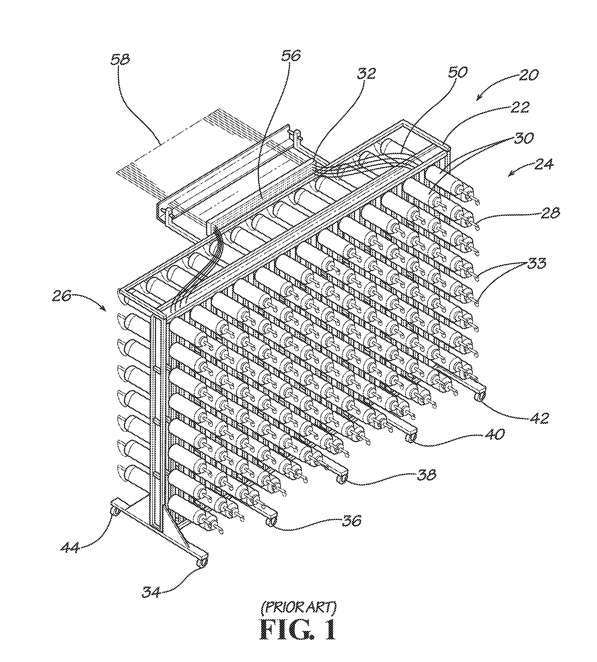
Known processes for providing yarn to tufting machines and otherwise using creels generally require significant factory space and other resources.

Method used


Image

  • Portable Creels With Insertable Yarn Trays and Improved Headers and Yarn Handling Methods
  • Portable Creels With Insertable Yarn Trays and Improved Headers and Yarn Handling Methods
  • Portable Creels With Insertable Yarn Trays and Improved Headers and Yarn Handling Methods

Examples


Embodiment Construction

[0045]Various innovations related to providing yarn for use on tufting machines and using yarn creels are disclosed herein. These innovations may be used in various combinations or separately. None of the features of any creel, header, or other component or any step of any process or method described herein should be considered essential or necessary to the disclosed invention. Rather this disclosure describes and enables various devices and methods that can include one or more of the various features presented herein to provide one or more of several possible benefits.

[0046]A. Frame for Holding Multiple Yarn Trays

[0047]Generally, disclosed below is a creel for feeding yarn from packages into a tufting machine FIG. 4 illustrates a creel 100 that includes a stationary header 600 positioned with respect to an intermediate header 300 and a detachable header 500. As described in detail below, the creel 100 utilizes a movable rack / frame 102 that receives a plurality of trays or container...


PUM


Abstract

Creels having frames configured to receive one or more trays of yarn packages. The trays of yarn packages are removable from the frame and can be loaded with packages of yarn when not inserted into the frame. Separately loading trays with yarns can simplify and provide other benefits with respect to the process of loading a creel with yarn packages. Also disclosed is an assembly that is positioned with respect to a detachable header and a stationary header on a creel and that comprises an air flow unit that causes yarns to move through to an alignment mechanism that aligns the yarns for attachment to yarns already feeding into a tufting machine.

Description

RELATED APPLICATIONS[0001]This application claims the benefit of U.S. Provisional Application Ser. No. 61 / 356,246 filed Jun. 18, 2010 titled “Creel Frames with Insertable Yarn Trays and Improved Headers,” the content of which is hereby incorporated by reference.FIELD OF THE INVENTION[0002]The field of this invention is systems and methods for manufacturing carpet, carpet tiles, and other products, using tufting machines, and more specifically, systems and methods for handling yarn supplied to tufting machines.BACKGROUND[0003]Tufting machines are used in the manufacture of various products. A tufting machine typically receives multiple yarns that are used by the tufting machine to create loops or tufts in a backing material. In many tufting machines, each of multiple adjacent needles uses a thread of yarn to tuft a row of tufts. Because many such needles may require different yarns simultaneously, many tufting machines require that multiple yarns be fed into or otherwise received by ...

Claims


Application Information

Patent Timeline
IPC IPC(8): D05C15/18B65H49/20D05C15/16D03J5/08
CPCB65H49/16B65H57/12B65H57/16D05C15/18B65H2701/31D02H1/00D03D39/06B65H67/02
Inventor INGRAM, III, WILLIAM OSCARJONES, WILLIAM N.BRADLEY, JR., HORACE EDDIE
Owner INTERFACE INC
Learn More