Method for determining spatial distribution of fluid injected into subsurface rock formations

a technology of fluid injection and spatial distribution, which is applied in the field of mapping the spatial distribution with respect to the time of fluid injection into subsurface rock formations, can solve the problems of insufficient resistivity/conductivity contrast, the range of detection through rock formations is not large enough, and the use of radioisotopes may be prohibited

Inactive Publication Date: 2011-12-22
SCHLUMBERGER TECH CORP
View PDF1 Cites 58 Cited by
  • Summary
  • Abstract
  • Description
  • Claims
  • Application Information

AI Technical Summary

Problems solved by technology

However, in a number of instances there is not a large enough resistivity / conductivity contrast between the injected fluid and fluid in the surrounding rock formation in order to use EM mapping techniques known in the art.
However, use of radioisotopes may be prohibited in certain areas, and their range of detectability through rock formations is generally limited to a distance of about one foot from the radiation detector.

Method used


Image

  • Method for determining spatial distribution of fluid injected into subsurface rock formations
  • Method for determining spatial distribution of fluid injected into subsurface rock formations
  • Method for determining spatial distribution of fluid injected into subsurface rock formations

Examples


Embodiment Construction

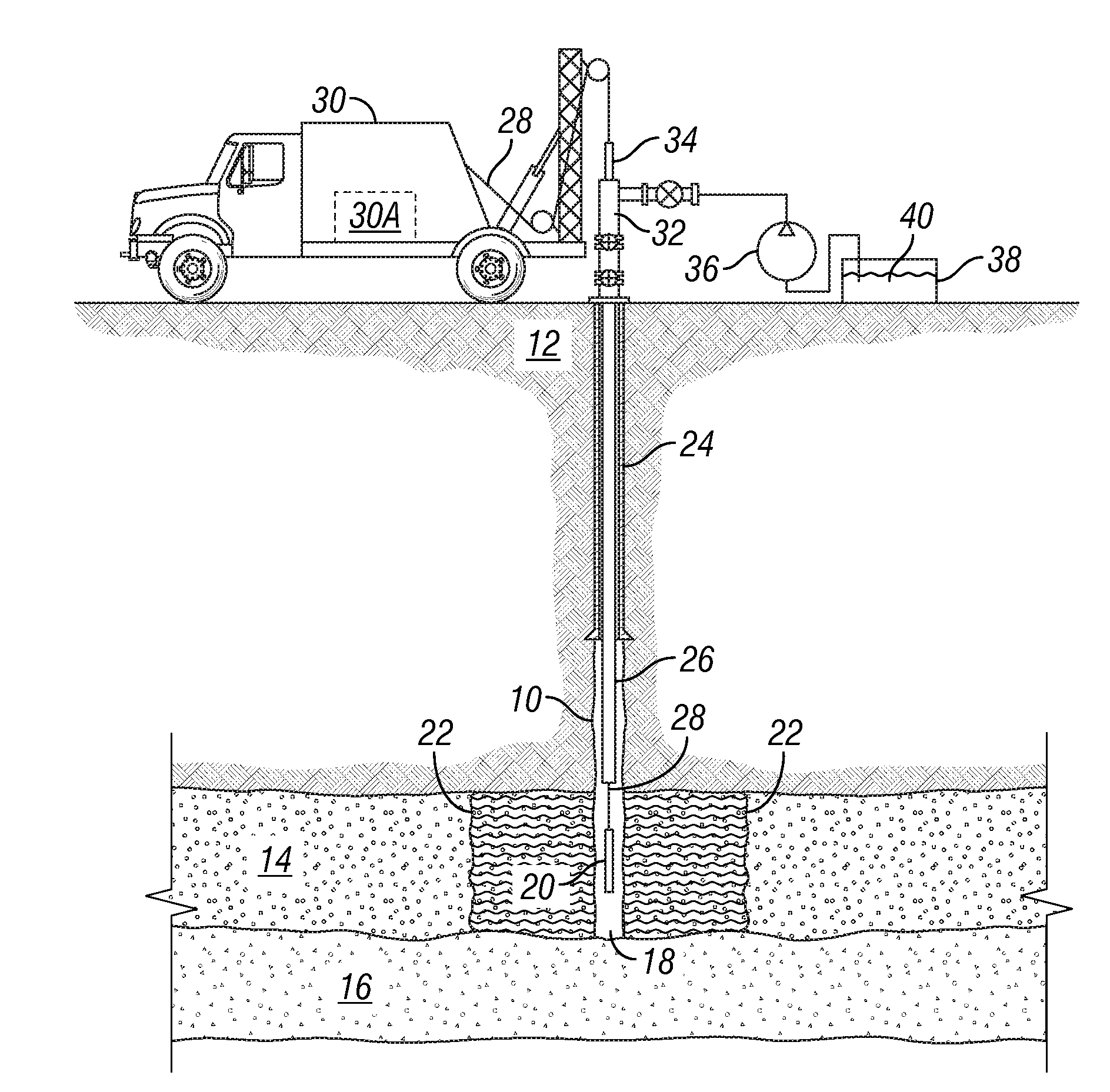
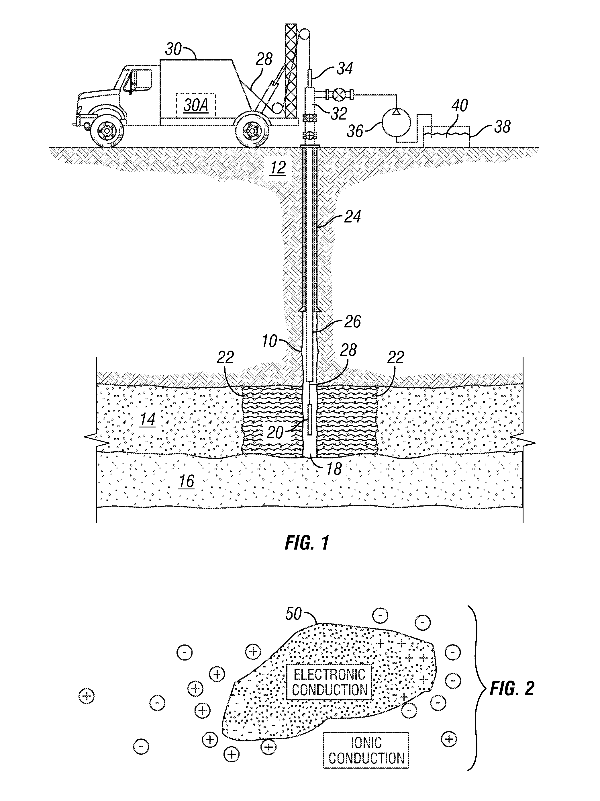
[0019]An example of injecting fluid into a subsurface formation through a wellbore and making EM measurements from within the same or different wellbore is shown schematically in FIG. 1. A wellbore 10 that may be used for fluid injection is drilled through subsurface rock formations, shown generally at 12, and into or through an injection formation 14. As explained in the Background section herein, the injection formation 14 is one in which fluid is to be injected, for example, to displace hydrocarbon or contaminants, and / or to maintain fluid pressure in the formation 14. It is desirable in certain circumstances to be able to determine the spatial distribution of the injected fluid and its boundary or “front”22 with respect to fluids already present in the pore spaces of the injection formation 14.

[0020]The example wellbore 10 may include a pipe or casing 24 cemented in place to a selected depth to protect shallower formations from fluid entry and to maintain the mechanical integrit...


PUM


Abstract

A method for determining spatial distribution of fluid injected into a subsurface rock formation includes injecting the fluid into the rock formation. The fluid includes therein electrically conductive solid particles dispersed in an electrolyte. An electromagnetic response of the formation is measured. The measured electromagnetic response is used to determine spatial distribution of the injected fluid.

Description

CROSS-REFERENCE TO RELATED APPLICATIONS[0001]Not applicable.STATEMENT REGARDING FEDERALLY SPONSORED RESEARCH OR DEVELOPMENT[0002]Not applicable.BACKGROUND OF THE INVENTION[0003]1. Field of the Invention[0004]The invention relates generally to the field of mapping spatial distribution with respect to time of fluids injected into subsurface rock formations. More specifically, the invention relates to methods for determining spatial distribution of an injected fluid in rock pore spaces when electrical conductivity contrast between the native (connate) fluid and the injected fluid is insufficient for conductivity based fluid mapping.[0005]2. Background Art[0006]Fluids are injected into subsurface rock formations for a number of different purposes, for example, to flush hydrocarbon from pore spaces in the formations and to move contamination or help remediate rock formations in environmental clean-up situations. For many such purposes, it is desirable that the spatial distribution of the...

Claims


Application Information

Patent Timeline
Patent Type & Authority Applications(United States)
IPC IPC(8): G01V3/30
CPCG01V3/00G01V3/24G01V3/26E21B47/113E21B47/00
Inventor BARBER, THOMAS D.ANDERSON, BARBARA I.TAHERIAN, REZALULING, MARTIN G.
Owner SCHLUMBERGER TECH CORP
Why Eureka
Try Eureka