Interface device, imaging system and method for rim-imaging

a technology of rim-imaging and interface device, which is applied in the direction of instruments, patient positioning for diagnostics, applications, etc., can solve the problems of so-called phase wrapping problem, strong jump of complex refraction index, and hamper the proper diagnosis of the lateral rim of the breast, so as to achieve the effect of increasing the lateral scan rang

Active Publication Date: 2011-12-22
KONINKLIJKE PHILIPS ELECTRONICS NV
View PDF8 Cites 4 Cited by
  • Summary
  • Abstract
  • Description
  • Claims
  • Application Information

AI Technical Summary

Benefits of technology

[0028]According to a further embodiment of the interface device, the device comprises two receptacles wherein each receptacle is adapted for receiving one object of interest. This embodiment has the advantage that it enables imaging of two objects simultaneously. When imaging female breasts, a device according to this embodiment can be used to image both breasts simultaneously or to image both breasts sequentially while having to fit the device to the patient only once.
[0029]It may be seen as a gist according to an exemplary embodiment of the invention, that a dedicated bra is designed. It consists of two layers. Between the two layers, a fluid or gel-like material is put that has a complex refractive index similar to the breast of the female patient. During compression, the gel is pushed towards the sides. Thus, direct contact of the breast with the two plates is achieved as wanted, but on the sides there is now the gel (or fluid) in addition. Thus, the lateral scan range may be increased and the rim of the breast may be imaged.

Problems solved by technology

One special problem with phase-contrast imaging is the so-called phase wrapping problem.
However, this is typically not the case at the rim of the object to be imaged (object of interest), where a strong jump of the complex refraction index is present due to the tissue-air interface.
This may prevent a proper phase retrieval at the rim of the breast and may hamper thus proper diagnosis at the lateral rim of the breast.
Consequently, tomography or tomosynthesis may become difficult, if not impossible.

Method used


Image

  • Interface device, imaging system and method for rim-imaging
  • Interface device, imaging system and method for rim-imaging
  • Interface device, imaging system and method for rim-imaging

Examples


Embodiment Construction

[0036]The illustration in the drawings is schematically and not to scale. In different drawings, similar or identical elements are provided with the same reference numerals.

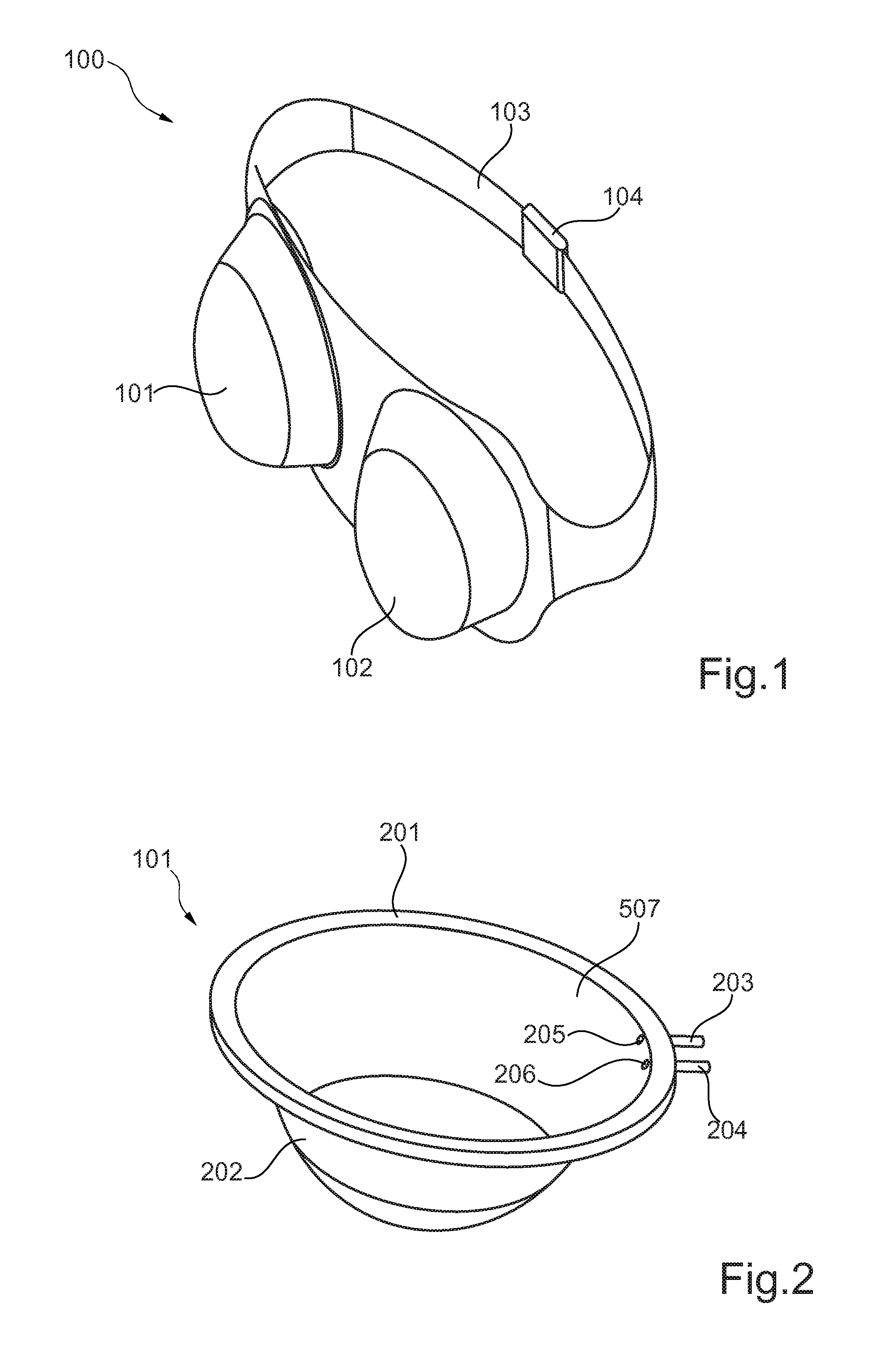
[0037]FIG. 1 shows an interface device for phase contrast rim-imaging of an object of interest, in particular for mammographic imaging of two female breasts.

[0038]The device 100 comprises two receptacles 101, 102, the first one being for the right breast and the second one being for the left breast of a patient.

[0039]Furthermore, the device 100 comprises a strap 103 for forcing the receptacles 101, 102 against the breasts and for securing the device around the chest of the patient. Furthermore, a fastener 104 is provided which is adapted for opening and closing the strap 103.

[0040]The strap 103 allows the force with which the device 100 is forced against the breasts to be adjusted allowing for patient comfort. The receptacles 101, 102 may at least partially be flexible to allow them to change the shape in accorda...


PUM


Abstract

The invention relates to imaging systems in which during imaging of an object a matching medium is used to match the object to its surroundings. An interface device is used for phase contrast rim-imaging of the object, which comprises a compartment in which a deformable matching material is contained which can be pushed to the side when the object to be imaged is compressed. Thus, a lateral field of view for X-ray phase contrast mammography may be increased.

Description

FIELD OF THE INVENTION[0001]The invention relates to an interface device for phase contrast rim-imaging of an object of interest, a mammographic imaging system and a method of phase contrast rim-imaging of an object of interest.BACKGROUND OF THE INVENTION[0002]X-ray phase contrast mammography has the potential to improve the diagnostic value of X-ray mammograms considerably. One special problem with phase-contrast imaging is the so-called phase wrapping problem. For instance, in the measurement setup with a Talbot interferometer with a pitch of p1 for the phase grating, phase information can be retrieved unambiguously only if the gradient of the phase front is less than 2 π / p1. This is typically achievable for a few cm of soft-tissue of constant thickness. However, this is typically not the case at the rim of the object to be imaged (object of interest), where a strong jump of the complex refraction index is present due to the tissue-air interface. This may prevent a proper phase re...

Claims


Application Information

Patent Timeline
Patent Type & Authority Applications(United States)
IPC IPC(8): A61B6/04G01T1/36
CPCA61B5/0091A61B6/0414A61B8/0825A61B6/502A61B6/484
Inventor KOEHLER, THOMAS
Owner KONINKLIJKE PHILIPS ELECTRONICS NV
Why Eureka
Try Eureka