

Inspection device for defect inspection
- Summary
- Abstract
- Description
- Claims
- Application Information
AI Technical Summary
Benefits of technology
Problems solved by technology
Method used
Image

Examples
Embodiment Construction
[0029]Exemplary embodiments of the invention will be described in detail with reference to the accompanying drawings.
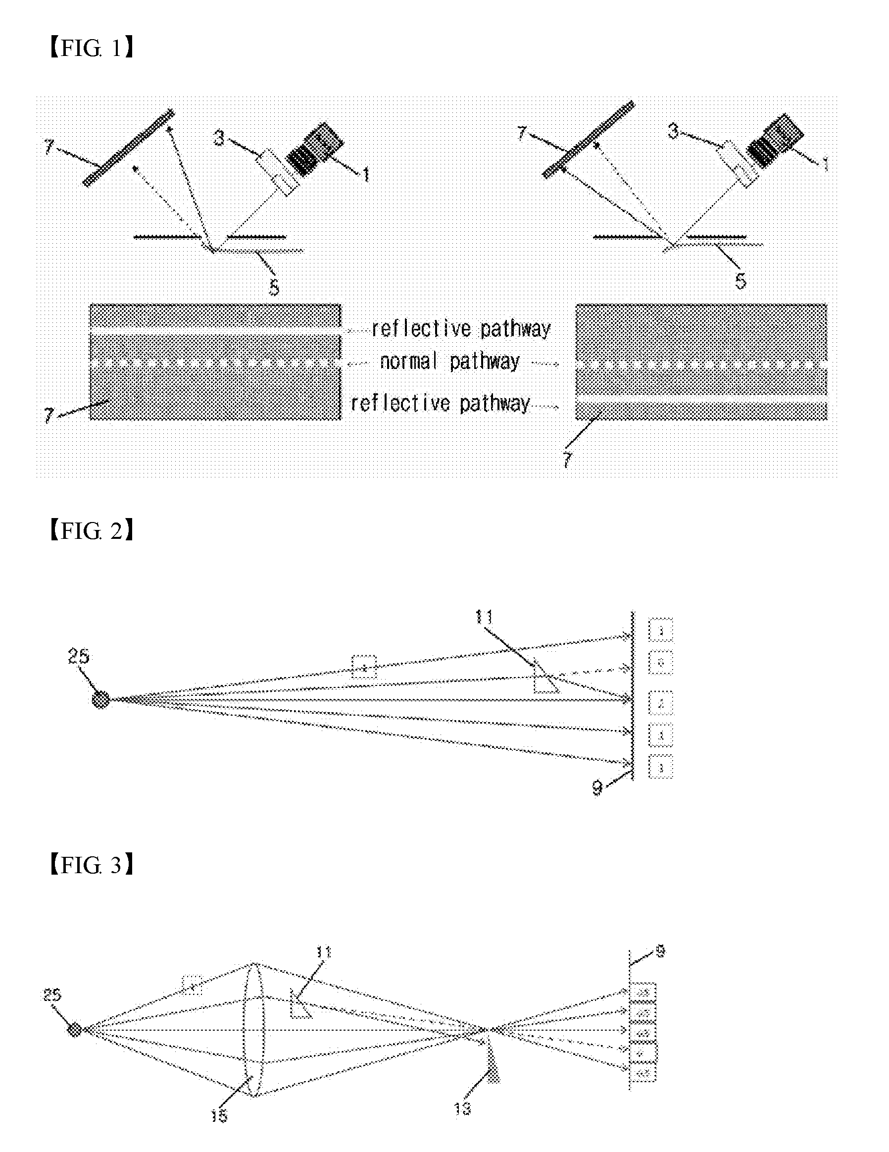
[0030]FIG. 3 is an optical diagram explaining a principle of a knife edge in an inspection device according to the present invention.
[0031]A point light source 25 is located on a left focal point of a field lens 15, and light emitted from the light source 25 is illuminated on a screen 9 through a right focal point of the field lens 15. When there is a defect 11 between the field lens 15 and the right focal point of the field lens 15, an optical pathway of light passing through the defect 11 is refracted from a normal optical pathway indicated by a dotted line to terminate instead of passing through an edge located on the right focal point, that is, a knife edge 13 which may have a sharp plate-shape end.
[0032]In addition, assuming that the intensity of light emitted from the light source 25 shown in FIG. 3 is the same as the intensity of light emitted from the light so...
PUM
 Abstract
Description
Claims
Application Information