
Electrode device for an electrochemical sensor chip

a sensor chip and electrode technology, applied in the direction of electrochemical variables of materials, contact material connections, instruments, etc., can solve the problems of reducing the reliability of measurement, reducing the detection sensitivity, and difficult for the electrode device to be used as a disposable product, so as to reduce the detection sensitivity and increase the size of the electrode device

Active Publication Date: 2014-04-08
JAPAN AVIATION ELECTRONICS IND LTD +1
View PDF9 Cites 0 Cited by
  • Summary
  • Abstract
  • Description
  • Claims
  • Application Information

AI Technical Summary

Benefits of technology

[0006]However in the electrode device as described in JP 2007-278981 A, the potential of the planar electrode device 2 in contact with a sample is extracted through the conductive pattern 3. Therefore, the electrode device necessarily has a long conduction path and is susceptible to electromagnetic noise and the like, possibly reducing the detection sensitivity. In addition, since the planar electrode device 2 and the conductive pattern 3 are formed in a planar extension on the insulation substrate 1, the size of the electrode device is increased and, when performing multi-point measuring, the whole measuring device requires a large size.
[0008]Thus, an object of the present invention is to provide an electrode device for an electrochemical sensor chip capable of highly-sensitive and highly-reliable measurement even when measuring a liquid sample and suitable for multi-point measurement and the use as a disposable product.

Problems solved by technology

Therefore, the electrode device necessarily has a long conduction path and is susceptible to electromagnetic noise and the like, possibly reducing the detection sensitivity.
On the other hand, when the sample 6 is a liquid sample containing a biologically derived substance, etc., the integrated circuit chip 4 as described in JP 2003-532090 A may allow the sample 6 to infiltrate into the integrated circuit chip 4 through fine cracks or the like in the insulation layer film covering the surface of the integrated circuit chip 4, possibly causing short-circuiting and thus reducing the reliability of measurement.
Further, the electrode 5 is secured to the surface of the integrated circuit chip 4 which is expensive, making it difficult for the electrode device to be used as a disposable product.
Further, it is impossible to dispose the electrode device by removing only the electrode 5 from the integrated circuit chip 4.

Method used


Image

  • Electrode device for an electrochemical sensor chip
  • Electrode device for an electrochemical sensor chip
  • Electrode device for an electrochemical sensor chip

Examples


embodiment 1

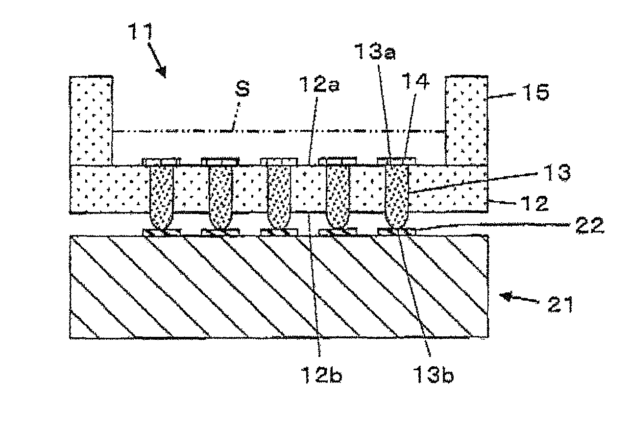
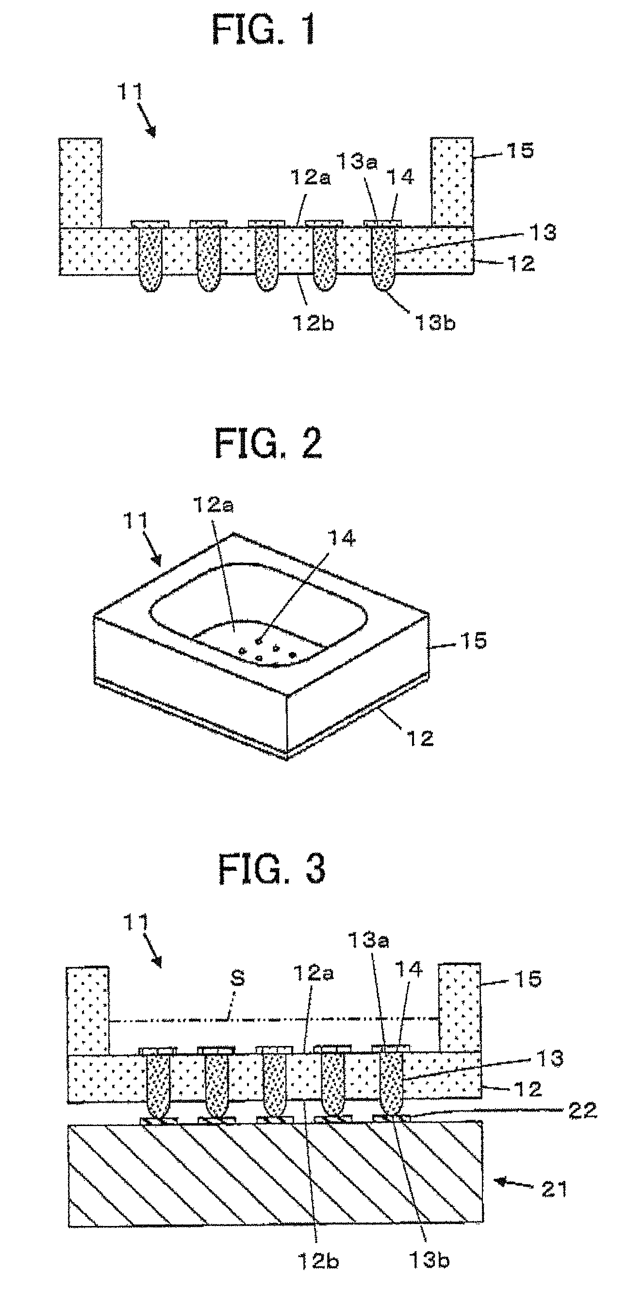
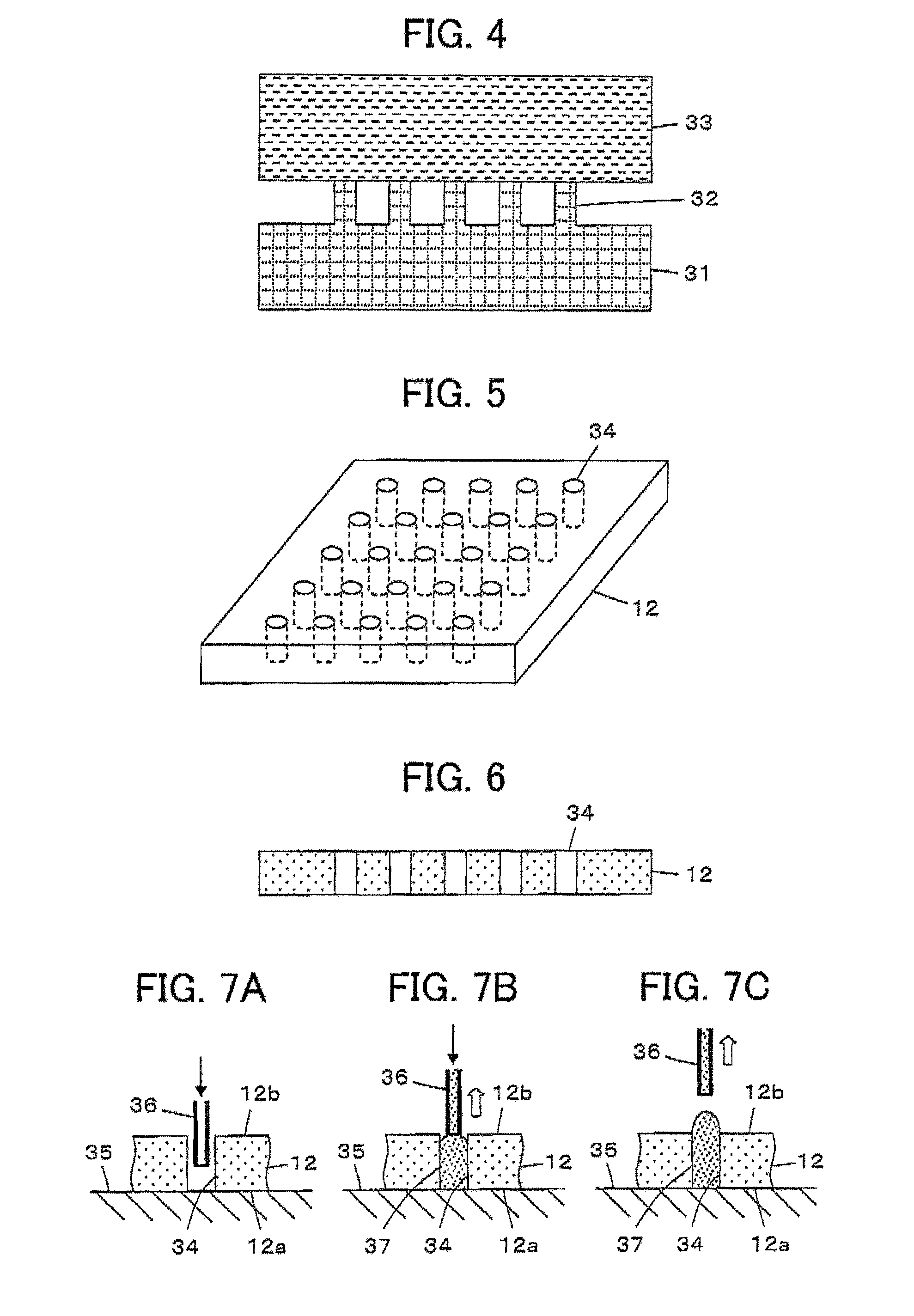
[0027]FIG. 1 illustrates a configuration of an electrode device 11 for an electrochemical sensor chip according to an embodiment 1 of the invention. The electrode device 11 for an electrochemical sensor chip comprises an insulation sheet 12 and electrode members 13 disposed in a matrix distribution at a given pitch in the insulation sheet 12. The insulation sheet 12 is made of an insulating material and comprises a top surface 12a and a bottom surface 12b opposite to each other in a thickness direction. The electrode members 13 are made of a conductive material and are held by the insulation sheet 12 in such a manner that the electrode members 13 pierce the insulation sheet 12 in the thickness direction from the top surface 12a through the bottom surface 12b. One ends 13a of the electrode members 13 are in the same plane as the top surface 12a of the insulation sheet 12 while the other ends 13b of the electrode members 13 project from the bottom surface 12b of the insulation sheet 1...

embodiment 2

[0051]FIG. 9 illustrates a configuration of an electrode device 41 for an electrochemical sensor chip according to embodiment 2. The electrode device 41 for an electrochemical sensor chip is equivalent to the electrode device 11 illustrated in FIG. 1 according to the embodiment 1 except that it additionally comprises a rigid frame 16 attached to the bottom surface 12b of the insulation sheet 12 in a position close to the periphery thereof. The frame 16 has the shape of a flat sheet having an opening 16a for exposing the other ends 13b of all the electrode members 13 projecting from the bottom surface 12b of the insulation sheet 12 and comprises a pair of extensions 16b extending beyond the insulation sheet 12 and the liquid reservoir member 15 as illustrated in FIG. 10. The extensions 16b each have a positioning hole 17.

[0052]According to the embodiment 2, the transducer 21 is secured to a fixing base 42, and a pair of positioning pins 43 project from the fixing base 42 on the oppos...

embodiment 3

[0058]While at least one of the insulation sheet 12 and the electrode members 13 preferably have elasticity, providing elastic members 54 made of a material such as silicone rubber between them as illustrated in FIG. 13 also allows an insulation sheet 52 having poor elasticity to hold electrode members 53 having poor elasticity. The elastic members 54 are so provided as to surround the respective electrode member 53. Such a structure provided with the elastic members 54 allows the electrode members 53 to displace in the insulation sheet 52 and therefore permits the use of the insulation sheet 52 made of a hard material such as acrylic, polycarbonate, glass, or ceramics and the use of the electrode members 53 made of a metallic material coated by Au to establish a good electric connection between the electrode members 53 held by the insulation sheet 52 and the electrodes 22 of the transducer 21.

[0059]Alternatively, another configuration may be made such that, as illustrated in FIG. 1...


PUM

PropertyMeasurementUnit
heightaaaaaaaaaa
diameteraaaaaaaaaa
depthaaaaaaaaaa

Abstract

An electrode device for an electrochemical sensor chip includes an insulation sheet having an insulating property and including a top surface and a bottom surface opposite to each other in a thickness direction, and electrode members having a conductivity and held by the insulation sheet with the electrode members piercing the insulation sheet in a thickness direction, one ends of the electrode members located on the top surface side of the insulation sheet being connected to an analyte, the other ends located on the bottom surface side of the insulation sheet being connected to an electrodes of a transducer.

Description

BACKGROUND OF THE INVENTION[0001]The present invention relates to an electrode device for an electrochemical sensor chip and particularly to a disposable electrode device for connecting any of analytes such as chemicals and biologically derived substances exemplified by DNA, proteins, antibodies, cells, and microorganisms to the electrodes of a transducer for detecting an analyte with an enhanced sensitivity using an electrochemical method.[0002]There are widely known in the fields of medicine, food, and environment techniques for detecting a trace amount of analyte existing in a sample with a high sensitivity. Generally, an electrochemical sensor chip comprises electrodes modified by a molecular recognition element formed of biologically derived substances, chemicals, and the like selectively reacting with an analyte in a sample. When a sample is brought into contact with these electrodes, effects produced by an interaction can be sensed by detecting a change in electric current us...

Claims


Application Information

Patent Timeline
Patent Type & Authority Patents(United States)
IPC IPC(8): G01N27/416G01N27/30G01N33/487
CPCG01N27/307G01N27/403G01N33/487
Inventor SUDA, ATSUSHIKIMURA, TATSUOKUNIKATA, RYOTAMATSUE, TOMOKAZU
Owner JAPAN AVIATION ELECTRONICS IND LTD
Learn More