Antireflection film, method for manufacturing antireflection film, and display apparatus

a technology of anti-reflection film and anti-reflection film, which is applied in the direction of identification means, instruments, other domestic objects, etc., can solve the problems of insufficient reflection prevention effect, difficult-to-see display, and insufficient reflected light beam removal. achieve the effect of low reflection

Active Publication Date: 2011-12-29
SHARP KK
View PDF4 Cites 9 Cited by
  • Summary
  • Abstract
  • Description
  • Claims
  • Application Information

AI Technical Summary

Benefits of technology

[0038]In the antireflection film of the present invention, the moth-eye structure itself of the antireflection film is improved to have an antiglare effect. Thus, the present antireflection film can easily achieve a low reflection effect and an antiglare effect without quality deterioration.

Problems solved by technology

Thus, these reflected light beams are not perfectly removed and the reflection preventing effect is insufficient.
As a result, only performing the LR treatment causes reflection of surrounding light at a certain reflectivity, so that images of a light source such as a fluorescent light appear on the display and cause hard-to-see display.

Method used


Image

  • Antireflection film, method for manufacturing antireflection film, and display apparatus
  • Antireflection film, method for manufacturing antireflection film, and display apparatus
  • Antireflection film, method for manufacturing antireflection film, and display apparatus

Examples


embodiment 1

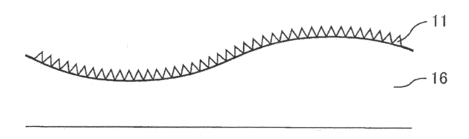
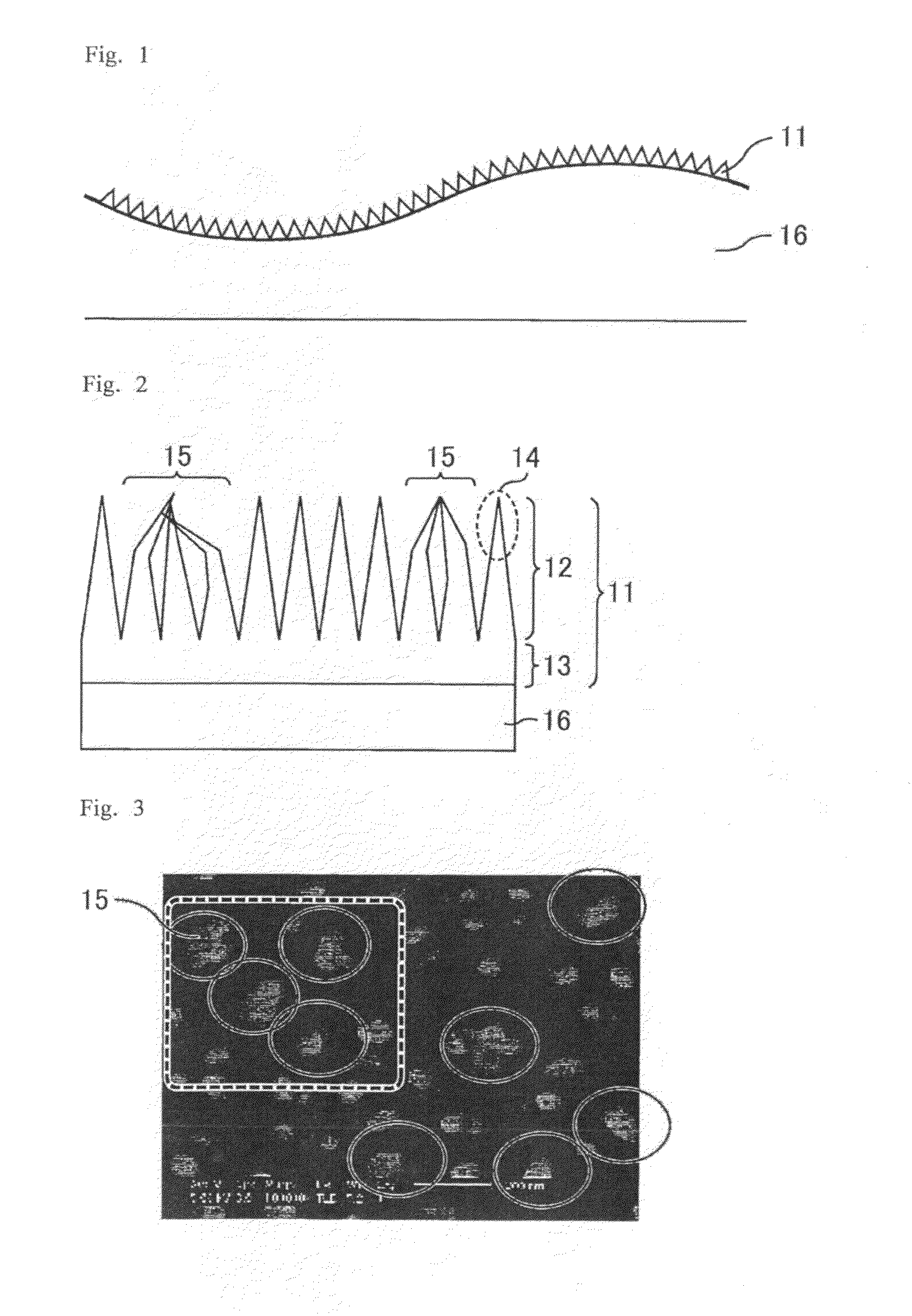
[0077]FIGS. 1 and 2 each are a schematic cross-sectional view of the moth-eye film (antireflection film) of Embodiment 1. FIG. 1 is an overall view and FIG. 2 is an enlarged view. As shown in FIGS. 1 and 2, a moth-eye film 11 of Embodiment 1 is disposed on a substrate 16 which is the target of antireflection treatment. The substrate 16 to be the target of antireflection treatment may be a member constituting the outermost surface of a display device, such as a polarizer, acryl protecting plate, or hard coat layer disposed on the surface of a polarizer.

[0078]As shown in FIG. 1, the moth-eye film 11 has a structure that multiple fine projections are arranged on its surface. Each of the projections is tapered toward the tip. The surface of the substrate 16 has an uneven structure with a gentler incline than the fine projections, and the surface of the moth-eye film 11 also has a corresponding gentle uneven structure. The surface of the substrate 16 is formed by the AG treatment. The di...

embodiment 2

[0098]The moth-eye film of Embodiment 2 is different from the moth-eye film of Embodiment 1 in that the material resin of the moth-eye film is different; however, the film of Embodiment 2 is the same as that of Embodiment 1 in the other respects. The following will describe the method for producing the moth-eye film of Embodiment 2 referring to Examples 5 and 6 wherein a moth-eye film was actually produced.

[0099]FIG. 19 is a plan photograph of the moth-eye film produced in Example 5 and FIG. 20 is a schematic view of the portion outlined by the dotted line in FIG. 19. In addition, FIG. 21 is a plan photograph of the moth-eye film produced in Example 6 and FIG. 22 is a schematic view of the portion outlined by the dotted line in FIG. 21. The steps in Examples 5 and 6 are substantially the same as those in Example 2, but they are different from those in Example 2 in that a resin material is not one to be cured at 2 J / cm2 but one to be cured at 6 J / cm2. The moth-eye film produced in Ex...

embodiment 3

[0102]The moth-eye film of Embodiment 3 is different from the moth-eye films of Embodiments 1 and 2 in that the surface of the moth-eye film is wet-wiped after applying ultraviolet rays to the resin layer to cure the layer; however, the film is the same as those in Embodiments 1 and 2 in the other respects. The following will describe the method for producing the moth-eye film of Embodiment 3 referring to Example 7 wherein a moth-eye film is actually produced.

[0103]FIGS. 23 to 28 are plan photographs of the moth-eye film produced in Example 7 and schematic views of the portion outlined by the dotted line in the corresponding photograph. FIGS. 23 and 24 are before wet-wiping, while FIGS. 25 to 28 are after wet-wiping. Of FIGS. 25 to 28, FIGS. 25 and 26 are not-enlarged views, while FIGS. 27 and 28 are enlarged views. The steps in Example 7 are substantially the same as those in Example 6, but they are different from those in Example 6 in that wet-wiping was performed using pure-water...


PUM

PropertyMeasurementUnit
diameteraaaaaaaaaa
diameteraaaaaaaaaa
aspect ratioaaaaaaaaaa

Abstract

The present application aims to provide an antireflection film having low reflectivity and suppressing glare. In at least one example embodiment, the antireflection film includes a surface that includes a moth-eye structure including multiple projections. Apexes of any two adjacent projections are apart from each other by a distance not longer than a wavelength of visible light. The moth-eye structure has sticking structures each of which includes projections with tip portions of the projections adhering to each other. Each of the sticking structures is 0.05 μm or greater and smaller than 1 μm in diameter. The sticking structures exist at a number density in planar area of the antireflection film of 0.01 pcs/μm2 or more and less than 20 pcs/μm2.

Description

TECHNICAL FIELD[0001]The present invention relates to an antireflection film, a method for producing an antireflection film, and a display device. The present invention specifically relates to an antireflection film having a moth-eye structure which apparently prevents a change in the refractive index at the interface between the air layer and the antireflection film and which allows the incident light to pass through the antireflection film without any change; a method suitable for producing such an antireflection film; and a display device comprising such an antireflection film.BACKGROUND ART[0002]Displays such as cathode ray tube (CRT) displays, liquid crystal displays (LCDs), plasma display panels (PDPs), and electroluminescence (EL) displays are required to have various functions, such as protection from damages, prevention of outdoor-light reflection, and protection from stains, on their surfaces.[0003]One means of imparting a function of preventing outdoor-light reflection is...

Claims


Application Information

Patent Timeline
Patent Type & Authority Applications(United States)
IPC IPC(8): G02B5/02G02B1/11G02B1/118G02F1/1335G09F9/00
CPCG02B1/118G02B5/021G02B5/201G02B5/02G02B5/20
Inventor MINOURA, KIYOSHIIMAOKU, TAKAOISURUGI, AKINOBU
Owner SHARP KK
Why Eureka
Try Eureka