Optical converting structure and led packing structure employing the optical converting structure

A technology of packaging structure and light conversion, which is applied in the direction of electrical components, circuits, semiconductor devices, etc., and can solve problems such as poor luminous efficiency and mutual absorption of excitation light

Inactive Publication Date: 2013-07-03
IND TECH RES INST
View PDF9 Cites 6 Cited by
  • Summary
  • Abstract
  • Description
  • Claims
  • Application Information

AI Technical Summary

Problems solved by technology

[0005] In view of the above problems, the purpose of the present invention is to provide a light conversion structure with a stacked structure and a packaging structure of light emittin...

Method used


Image

  • Optical converting structure and led packing structure employing the optical converting structure
  • Optical converting structure and led packing structure employing the optical converting structure
  • Optical converting structure and led packing structure employing the optical converting structure

Examples


Embodiment Construction

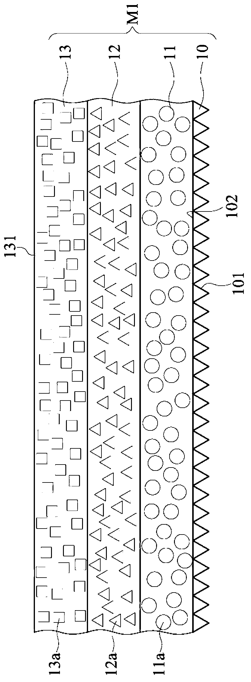
[0032] Please refer to Figure 1A , which is a schematic cross-sectional view of a light conversion structure according to an embodiment of the present invention. The light conversion structure M1 of this embodiment includes a first microstructure layer 10 and a plurality of phosphor layers (shown as phosphor layers 11 to 13 , but not limited to the present invention). The phosphor layers 11 to 13 are stacked to form a stacked structure. The first microstructure layer 10 includes a first flat surface 102 and a first rough surface 101 . The stack structure is disposed on the first flat surface 102 of the first microstructure layer 10 .

[0033] When light enters the first microstructure layer 10 from the first rough surface 101 of the first microstructure layer 10, since the refractive index inside the light conversion structure M1 is different from that outside the light conversion structure M1, and the first rough The surface 101 can change the incident angle of the light, ...


PUM


Abstract

The invention discloses an optical switching structure and an LED packaging structure. The optical switching structure includes a first microstructure layer and a stack structure formed by stacking a plurality of fluorescent powder layers. The first microstructure layer includes a first flat face and a first rough face. Light is emitted from the first rough face and emitted out from the first flat face after penetrating through the first microstructure layer and forming a plurality of first scattered light. The stack structure is arranged on the first flat face for absorbing the first scattered light emitted from the first flat face and exciting light.

Description

technical field [0001] The invention relates to a packaging structure of a light emitting diode, in particular to a light conversion structure with at least one microstructure and the packaging structure of a light emitting diode applied thereto. Background technique [0002] With the improvement of luminous efficiency of white light emitting diode (LED, Light Emitting Diode), white light LED has become a new generation light source that has attracted much attention. [0003] Most of the current white light LEDs use blue chips to excite phosphor powder to form white light, and the optical quality after conversion to white light is judged by the brightness, color rendering, and light distribution of the light source, and the color rendering of the light source is determined by the phosphor powder. The method of mixing determines that most of the phosphor powders of various wavelengths are mixed together to increase the color rendering. However, due to the mixing of various ph...

Claims


Application Information

Patent Timeline
IPC IPC(8): H01L33/50H01L33/58
Inventor 林建宪彭耀祈谢岷宜陈于堂徐达伟
Owner IND TECH RES INST
Why Eureka
Try Eureka