Imaging device with focused illumination

a high-resolution, imaging device technology, applied in the direction of printers, instruments, camera focusing arrangement, etc., can solve the problems of inconvenient and time-consuming nature of performing an initial inspection, inconvenient frequent limited use of pipe crawlers, etc., to facilitate long-range viewing, excellent imaging capability, and low power consumption

Active Publication Date: 2011-12-29
ENVIROSIGHT
View PDF2 Cites 21 Cited by
  • Summary
  • Abstract
  • Description
  • Claims
  • Application Information

AI Technical Summary

Benefits of technology

[0010]The present invention facilitates long-range viewing by providing imaging system having a light source and reflector that has an axis essentially coincident with that of the imaging device. More specifically, the imaging system comprises a parabolic reflector that is placed behind a high-zoom, imaging device such that the axis of the reflector and the optical axis of the imaging device are essentially coincident.
[0011]Such a configuration offers significant benefits. First, because the light and camera axes are essentially coincident, the device offers excellent imaging capability at far range with relatively little power expended on lighting. Because the present invention uses light more efficiently, less power is required to operate it. This has compounding benefits. For example, the reduction in power allows the system to use batteries instead of a supply cable if desirable. Furthermore, in one embodiment, the power may be supplied by batteries at the head of the device, thereby eliminating the need to supply power through a cable and a remote battery supply. Such an embodiment avoids the inherent voltage drop associated with transmitting power along a lengthy cable, thereby further reducing the power required to operate the imaging system. Thus, the present invention may realize compounded energy savings in certain embodiments.
[0012]There is also the benefit of reducing the bulk of the cable reaching the cable head and improving the overall maneuverability of the device, as the device no longer needs to be attached to a separate power supply. Furthermore, even if a remote power supply is still used, the reduced power requirements of the imaging system of the present invention reduce the gauge of the cable needed, and thus lighten the system and improve its maneuverability.
[0014]Another benefit of the camera system is that it promotes a single enclosure. There is no longer a need to machine separate housings for the lights and the imaging devices. They are all contained within a single, modular housing comprises one or more integrated components. Additionally, such a configuration has very few moving parts, which not only reduces mechanical wearing, but also reduces weight and inventory requirements and simplifies manufacturing.
[0015]Therefore, the configuration of the present invention uses light more efficiently to improve imaging performance, reduce power consumption, to provide a less-encumbered, simplified package, making it more maneuverable and readily manufactured than prior art inspection devices.
[0017]Yet another aspect of the invention is a modular lamp assembly for precisely positioning the point of light of a lamp in a certain position in a parabolic reflector to optimize light output. Specifically, Applicants have developed a modular lamp assembly that allows a particular lamp to be “tuned” for a parabolic reflector to compensate for manufacturing variations in the individual lamps. Once the assembly is tuned for a parabolic reflector, it may be used with any similar parabolic reflector. (Variations among parabolic reflectors tend to be small.) In one embodiment, the modular lamp assembly comprises: (a) a lamp; (b) a first bracket for holding said lamp; (c) a second bracket for holding said first bracket and being secured to an interface of a parabolic reflector; (d) one or more first adjustment screws between said first and second brackets configured to move said first bracket with respect to the second bracket; and (e) one or more second adjustment screws between said second bracket and said interface configured to move the second bracket with respect to said interface.

Problems solved by technology

These conditions include, for example, small confined spaces and harsh environments such as insufficient air / oxygen, presence of toxins, radioactivity, contamination, excessive dust, dirt and filth, and high noise levels.
Although each area presents its own problems and complexities with respect to inspecting and maintaining, the inconvenient and time-consuming nature of performing an initial inspection is common to all.
Although effective in obtaining detailed images, using a pipe crawler is inconvenient and requires a great deal of time to set up and operate even if no problem is discovered.
Furthermore, the use of pipe crawlers is frequently limited by the size and configuration of pipes to be entered.

Method used


Image

  • Imaging device with focused illumination
  • Imaging device with focused illumination
  • Imaging device with focused illumination

Examples


Embodiment Construction

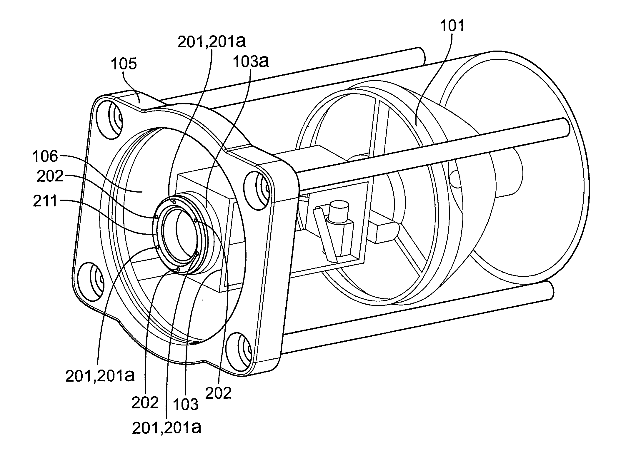
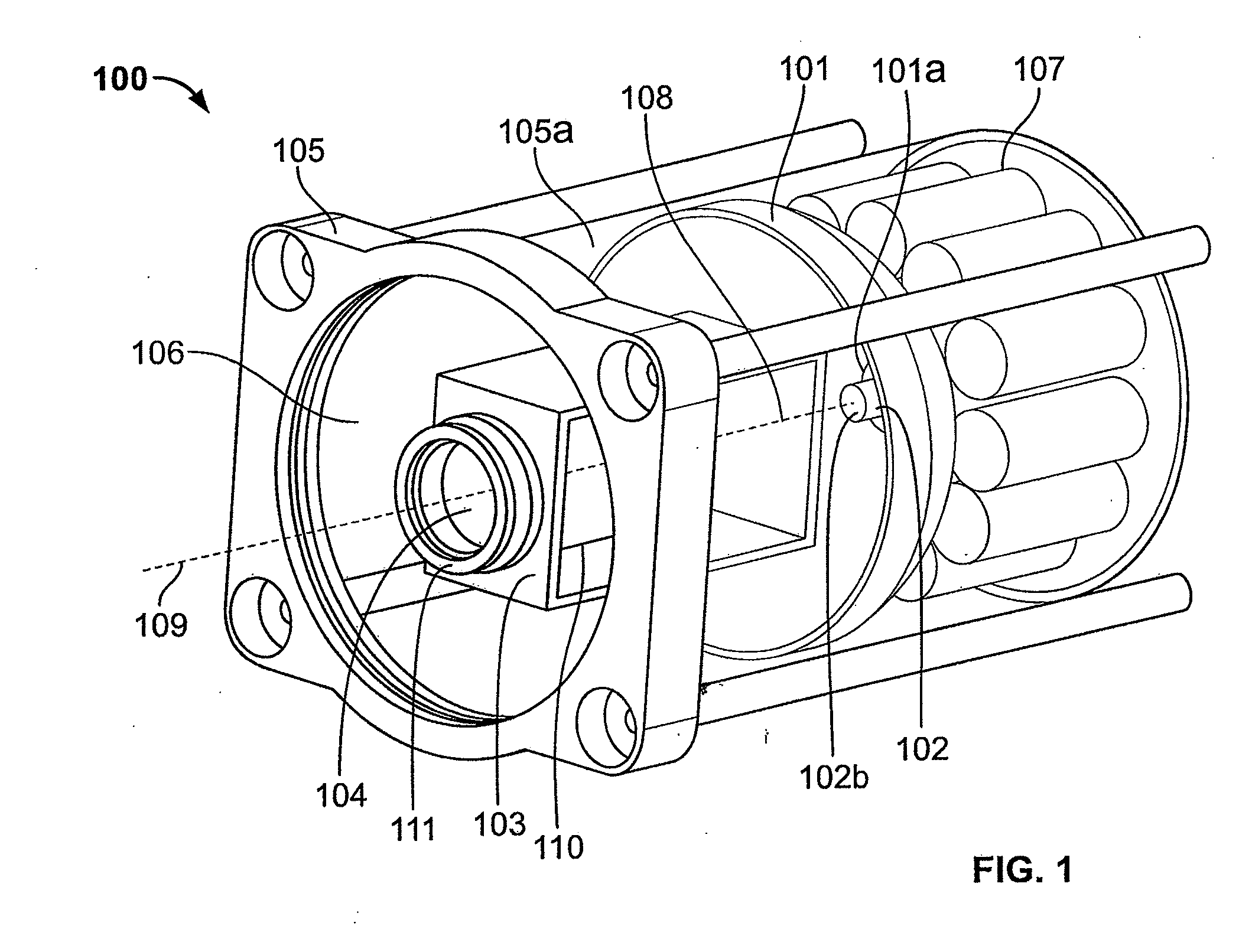
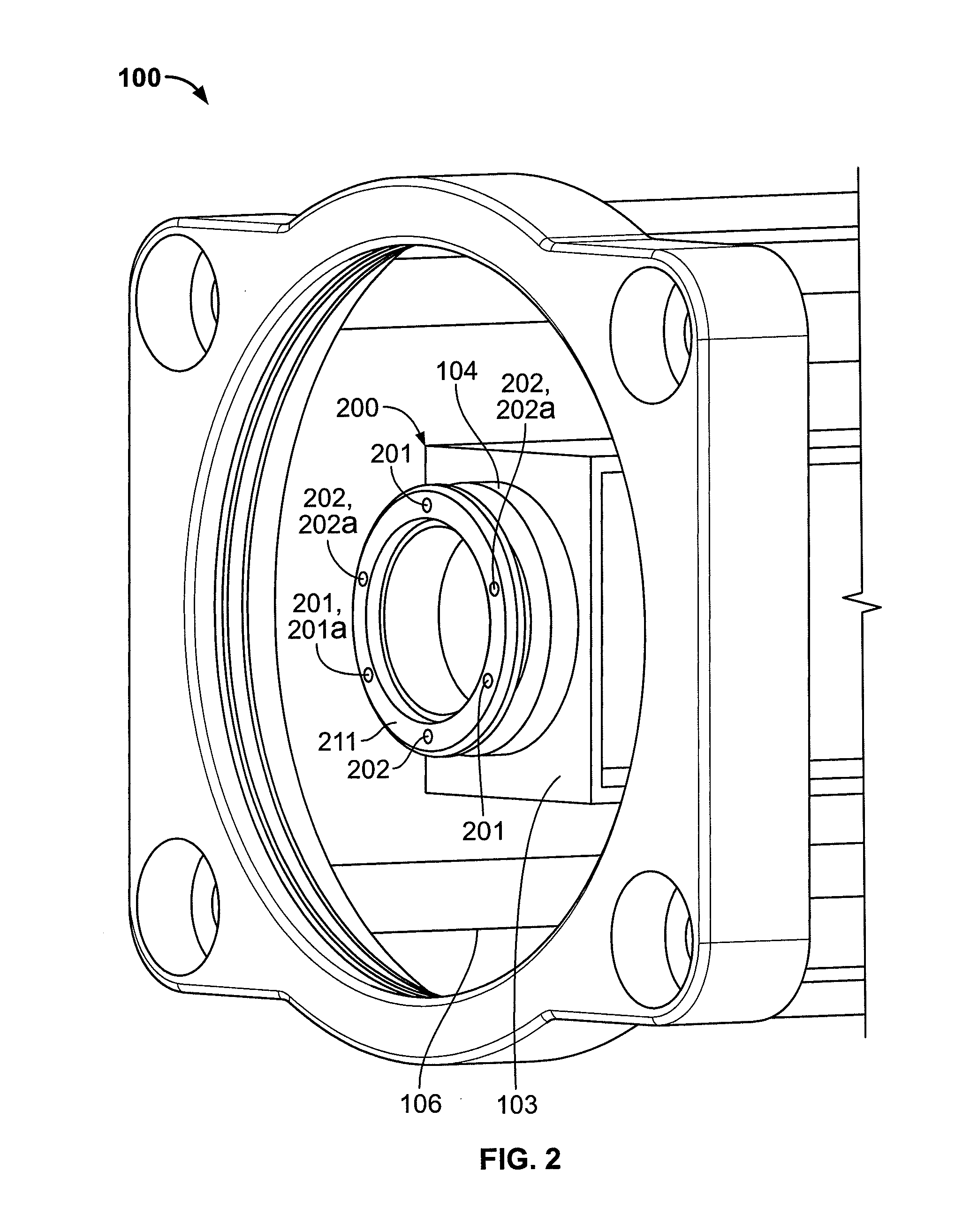
[0035]Referring to FIG. 1, one embodiment of an imaging system 100 of the present invention is depicted schematically. The imaging system 100 comprises: (a) a parabolic reflector 101 having a base 101a and defining a first axis 108; (b) a light source 102 disposed proximate the base 101a; (c) an imaging device 103 comprising a zooming lens 104 and having a second axis 109. The imaging device is disposed in front of the light source 102 such that the second axis 109 is essentially coincident with the first axis 108.

[0036]Each of these elements is considered in greater detail below and with respect to examples of alternative embodiments. It should be understood, however, that the classification of the system in these discrete elements is for illustrative purposes and should not be construed to limit the scope of the invention. For example, it is anticipated that two or more elements may correspond to a single component or the functionality of one element may correspond to two more com...


PUM


Abstract

An imaging system comprising a parabolic reflector having a base and defining a first axis, a light source disposed proximate the base essentially along the first axis, an imaging device comprising a zooming lens having a second axis, the imaging device being disposed in front of the light source along the first axis such that the second axis and the first axis are essentially coincident.

Description

REFERENCE TO RELATED APPLICATIONS[0001]This application claims priority to U.S. Provisional Application No. 61 / 357,763, filed Jun. 23, 2010, and U.S. Provisional Application No. 61 / 485,326, filed May 12, 2011, both of which are incorporated by reference in their entirety.FIELD OF INVENTION[0002]The present invention relates generally to a high-zoom imaging device for imaging objects at far range in limited light. More specifically, the invention relates to an imaging system in which the lighting and imaging devices are packaged to make their axes essentially coincident to facilitate high-zoom imaging in low-light conditions.BACKGROUND OF THE INVENTION[0003]It is often necessary to inspect and maintain areas under conditions that render them inaccessible or otherwise uninhabitable for humans for an extended period. These conditions include, for example, small confined spaces and harsh environments such as insufficient air / oxygen, presence of toxins, radioactivity, contamination, exce...

Claims


Application Information

Patent Timeline
Patent Type & Authority Applications(United States)
IPC IPC(8): F21V7/06G02B27/02
CPCG03B3/02G03B15/05G03B15/03F21V17/02H04N7/183G03B2215/0525G03B2215/0589
Inventor DROST, JEFFREY D.WALKER, JAMES WILLIAMLYNCH, CHRISLINDNER, RICHARD
Owner ENVIROSIGHT
Why Eureka
Try Eureka