
Asynchronous wireless communication system

a wireless communication and asynchronous technology, applied in the direction of synchronisation arrangement, instruments, measurement devices, etc., can solve the problems of deprived of key information, geo-location techniques used in synchronous networks cannot be applied directly to asynchronous wireless communication systems, and it is much more difficult to derive a measurement of the location of a wireless communication unit from signal timing information, etc., to achieve the effect of ‘processing gain

Active Publication Date: 2011-12-29
VIAVI SOLUTIONS UK
View PDF8 Cites 19 Cited by
  • Summary
  • Abstract
  • Description
  • Claims
  • Application Information

AI Technical Summary

Benefits of technology

[0048]In the prior art, accurate timing measurements are often viewed as coming from network analyzer equipment. However, the invention allows the derivation of network timing information from one or more wireless communication devices, even if the devices suffer from noise. While any one wireless device measurement is intrinsically noisy, the use of many measurements in concert permits a ‘processing gain’. As a result of this gain, the timing offset(s) may be estimated in an accurate manner.

Problems solved by technology

So in an asynchronous network, it is much more difficult to derive a measurement of the location of a wireless communication unit from signal timing information.
Geo-location techniques that are used in synchronous networks cannot be applied directly to asynchronous wireless communication systems.
In effect, the lack of a known and constant timing offset Tb for each base station deprives these techniques of a key piece of information.
This can greatly limit geo-location accuracy in asynchronous networks.
In real networks of the prior art, this problem is usually considered insoluble.
However, this determination requires prior knowledge of the locations of the mobiles.
However, a precise geo-location strategy will be limited, due to highly-variable signal fading effects.
When a user is inside a building, one cell site may appear weaker than another, due to different numbers of brick walls lying in the signal paths to each cell site.
A measurement of distance based on received and transmitted signal powers is therefore of limited applicability.

Method used


Image

  • Asynchronous wireless communication system
  • Asynchronous wireless communication system
  • Asynchronous wireless communication system

Examples


Embodiment Construction

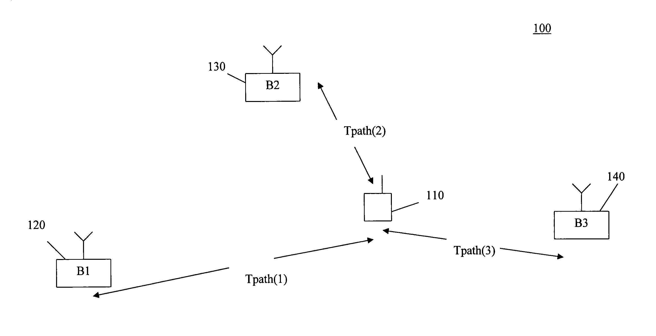
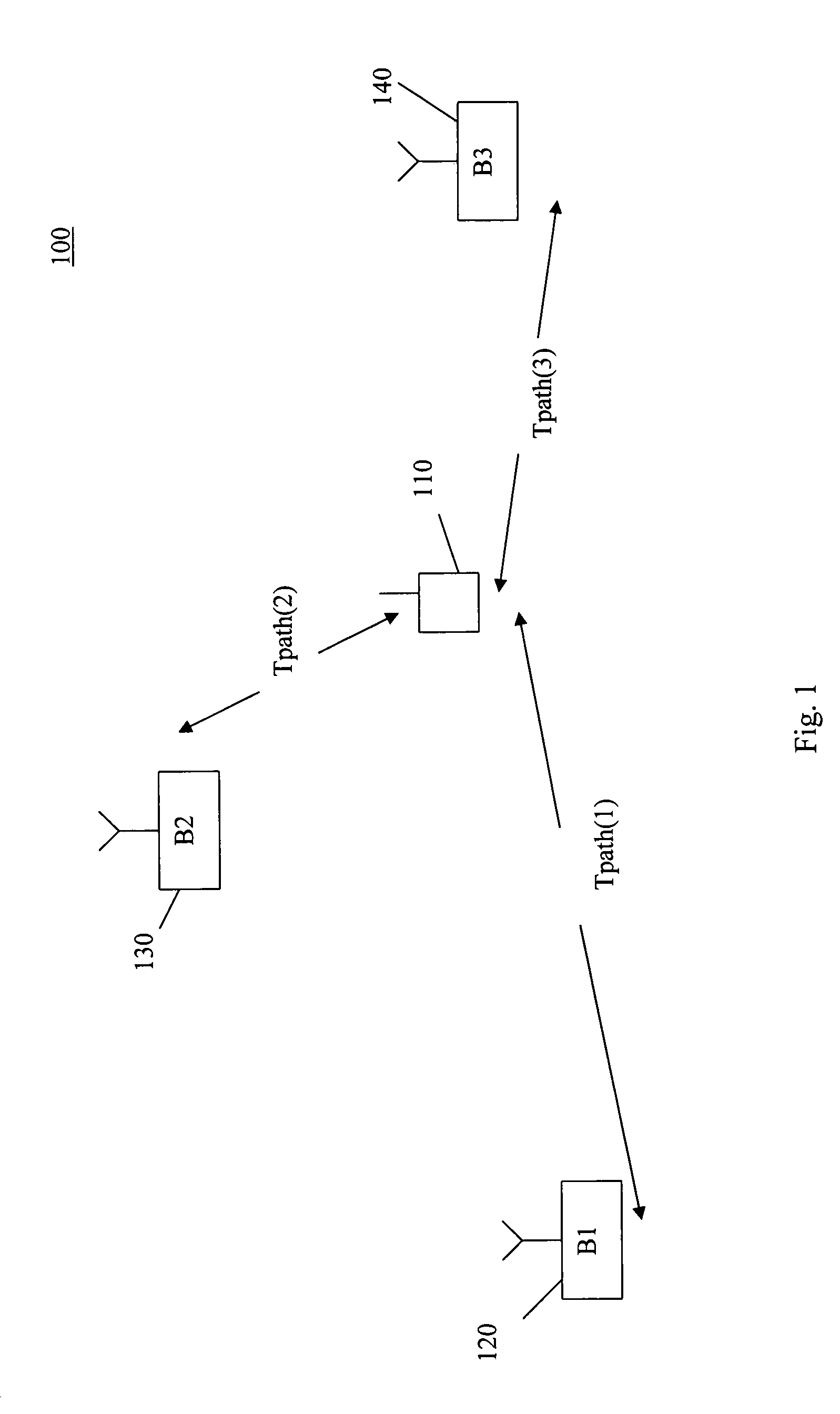
[0055]The present invention allows an estimation of the timing offset of base stations in an asynchronous telecommunications network. The present invention may provide an estimation of timing offsets even in asynchronous telecommunications systems, such as UMTS, with timing offsets that are initially unknown, and which change over time.

[0056]Normally, a wireless communication unit can ‘observe’ more than one base station at any given time, i.e., the mobile can receive signals from more than one base station. Equations of the form of [2] and [3]-[5] above can therefore be constructed for the signals received from each base station.

[0057]When a wireless communication unit can receive signals from two base stations simultaneously, the wireless communication unit has two measurements available for the ‘measured time’ Tm. Taking the difference between any two such measurements yields an equation of the form of equation [6] below.

dTm=Tm1−Tm2=dT path+dTb  [6]

[0058]Where:

[0059]‘d’ indicates...


PUM


Abstract

The invention relates to an asynchronous wireless communication system, such as a UMTS system. The various base stations of an asynchronous wireless communication system do not typically have known timing offsets Tb(i), and these timing offsets vary with time. The invention allows the calculation of the difference dTb(i,j) between timing offsets Tb(i), Tb(j) for pairs of base stations B(i), B(j), using the timing of signals received by one or more wireless communication units. Having eliminated the timing offsets between the base stations as a variable, geo-location techniques from synchronous networks may then be used to locate wireless communication units in the asynchronous wireless communication system.

Description

CROSS-REFERENCE TO RELATED APPLICATION[0001]This application claims priority under 35 U.S.C. §119 to U.S. Provisional Application No. 61 / 146,485, filed Jan. 22, 2009, the entire disclosure of which is incorporated herein by reference.FIELD OF THE INVENTION[0002]Aspects of the invention relate to the determination of base station timing differences in an asynchronous wireless communication system, and to the geo-location of wireless communication units in an asynchronous wireless communication system. The invention is applicable to asynchronous mobile telephone networks, but is not limited to these networks.BACKGROUND OF THE INVENTION[0003]A wireless communication unit usually forms part of a wireless communication system. The wireless communication unit communicates through a wireless communication network, which also forms part of the wireless communication system.[0004]An example of a wireless communication unit is a mobile telephone in a mobile telephone system. The terms ‘mobile...

Claims


Application Information

Patent Timeline
IPC IPC(8): H04W24/00
CPCH04W64/006G01S5/021H04W56/0065
Inventor FLANAGAN, MICHAEL JOSEPH
Owner VIAVI SOLUTIONS UK
Learn More