
System and Method for Identifying Defects of Surfaces Due to Machining Processes

a technology of surface defects and machining processes, applied in the field of simulation of machining processes, can solve the problems of difficult to see, small discrepancies between the actual the desired final shape of the workpiece, and achieve the effect of reducing memory requirements

Active Publication Date: 2011-12-29
MITSUBISHI ELECTRIC RES LAB INC
View PDF3 Cites 26 Cited by
  • Summary
  • Abstract
  • Description
  • Claims
  • Application Information

AI Technical Summary

Benefits of technology

[0017]It is a further object of this invention to provide such method that reduces memory requirement without compromising a quality of defect identification.

Problems solved by technology

The G-Code generated by the CAM system may not produce an exact replication of the desired shape.
In addition, the movement of the NC tool is governed by motors of the NC machining system, which have limited speeds, ranges of motion, and abilities to accelerate and decelerate, so that the actual tool motions may not exactly follow the NC machining instructions.
Discrepancies between the actual final shape of the workpiece and the desired final shape of the workpiece can be very small, and difficult to see.
In some situations, these discrepancies result in undesirable gouges or nicks in the surface of the final shape of the workpiece with sizes on the order of a few micrometers in depth and width, and tens of micrometers in length.
However, this manual testing is time consuming and expensive.
Thus, the defects in molds and dies can be undesirably transferred to the manufactured parts.
A die to stamp large parts that have a free-form shape can be very time consuming to produce due to both its size (1000's of millimeters) and because free-form surface are milled using relatively small tools (order of millimeters) requiring a large number of machining instructions (often millions).
The problem of locating these small defects is quite challenging.
For example, a human operator must painstakingly explore the entire simulated mold at a fine scale, which is time consuming and prone to errors.
However, that method is limited only to defects caused by local variations in the tool path because that method only considers the relationship between consecutive points on the machining path, and does not consider defects caused by adjacent paths of the machining tools and / or adjacent regions on the surface.

Method used


Image

  • System and Method for Identifying Defects of Surfaces Due to Machining Processes
  • System and Method for Identifying Defects of Surfaces Due to Machining Processes
  • System and Method for Identifying Defects of Surfaces Due to Machining Processes

Examples


Embodiment Construction

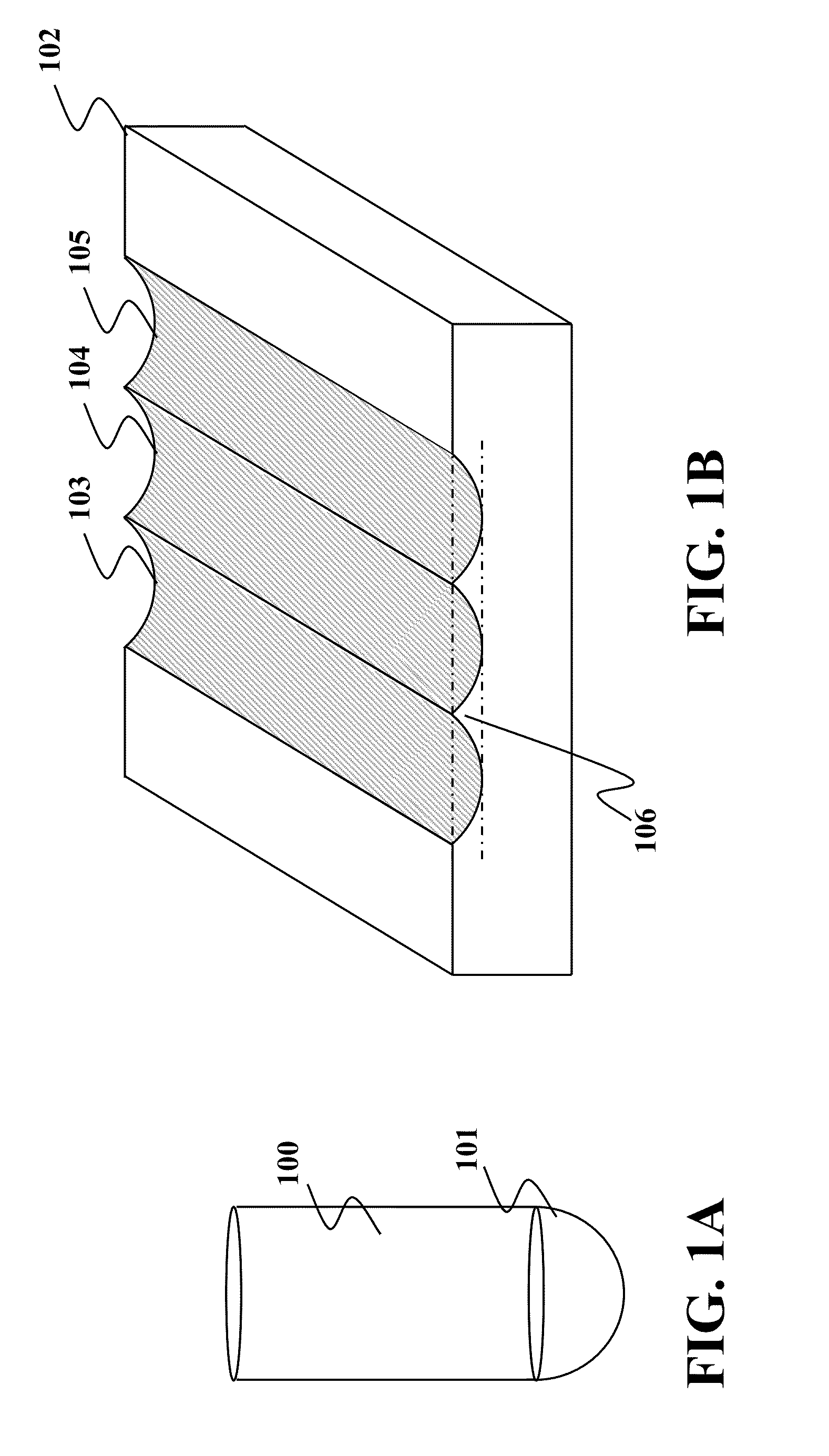
[0032]FIG. 1A shows a ball end milling cutter 100 commonly used to fabricate free-form surfaces during numerically controlled (NC) machining. In particular, a smooth hemispheric bottom 101 of a cutter 100 is capable of machining smooth surfaces.

[0033]FIG. 1B shows an object 102 milled by three linear cuts 103, 104 and 105 of the ball end milling cutter 100 producing semi-cylindrical surfaces. Between each of the cuts there is a triangular cusp formed by an intersection of each pair of cuts. For example between cuts 103 and 104 there is a cusp 106.

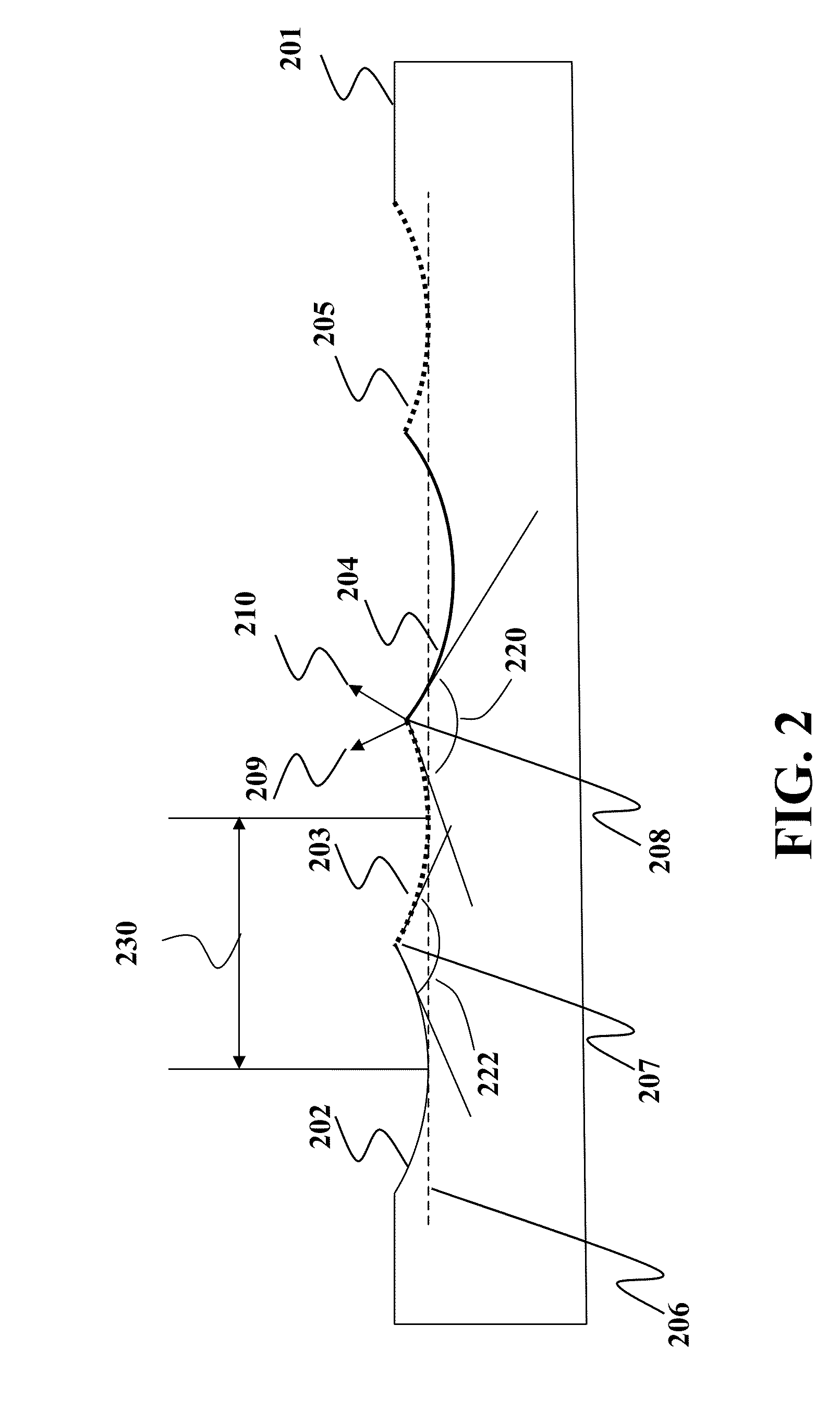
[0034]FIG. 2 is a side view of an object 201 milled by four cuts 202-205 of the ball end milling cutter. The cuts 202, 203 and 205 have an identical depth indicated by a dashed line 206. However, the cut 204 is deeper than the cuts 202, 203 and 205. Each pair of the cuts meets at the cusp. For example, the cut 202 and the cut 203 meet at the cusp 207 and the cut 203 and the cut 204 meet at the cusp 208. Because the cut 204 is deeper than th...


PUM


Abstract

Embodiments of the invention disclose a method for determining defects of a surface of a model of an object generated from a model of an original object by a simulation of a machining process. The method determines orientations and rate of change in the orientation of the surface based on normal vectors to the surface and identifies the defects of the surface based on the rate of change and a threshold. The threshold is determined based on the machining process.

Description

FIELD OF THE INVENTION[0001]The invention relates generally to a simulation of a machining process, and more particularly to identifying defects of a surface of an object from a model of the object rendered during the simulation.BACKGROUND OF THE INVENTIONNumerically Controlled Machining[0002]Simulation of the process of numerically controlled (NC) machining is of fundamental importance in computer aided design (CAD) and computer aided manufacturing (CAM). During the simulation, a computer model of a workpiece is edited with a computer representation of an NC machining tool and a set of NC machining tool motions to simulate the machining process. The workpiece model and tool representation can be visualized during the simulation to detect potential collisions between parts, such as the workpiece and the tool holder, and to verify the final shape of the workpiece after the simulation.[0003]The final shape of the workpiece is affected by the selection of the tool and the tool motions....

Claims


Application Information

Patent Timeline
Patent Type & Authority Applications(United States)
IPC IPC(8): G05B19/4097
CPCG05B19/41875G05B2219/32222G05B2219/32189Y02P90/02
Inventor SULLIVAN, ALANYOGANANDAN, ARUN R.
Owner MITSUBISHI ELECTRIC RES LAB INC
Features
  • Generate Ideas
  • Intellectual Property
  • Life Sciences
  • Materials
  • Tech Scout
  • Unparalleled Data Quality
  • Higher Quality Content
  • 60% Fewer Hallucinations
Learn More