
Remote control adjustable threshing cage vane system and method

a thresher and remote control technology, applied in the field of adjustable thresher cage vane, can solve the problems of high rotor speed, cracking and other damage of grains, and undersized concave gap siz

Inactive Publication Date: 2011-12-29
CNH IND AMERICA LLC
View PDF3 Cites 54 Cited by
  • Summary
  • Abstract
  • Description
  • Claims
  • Application Information

AI Technical Summary

Benefits of technology

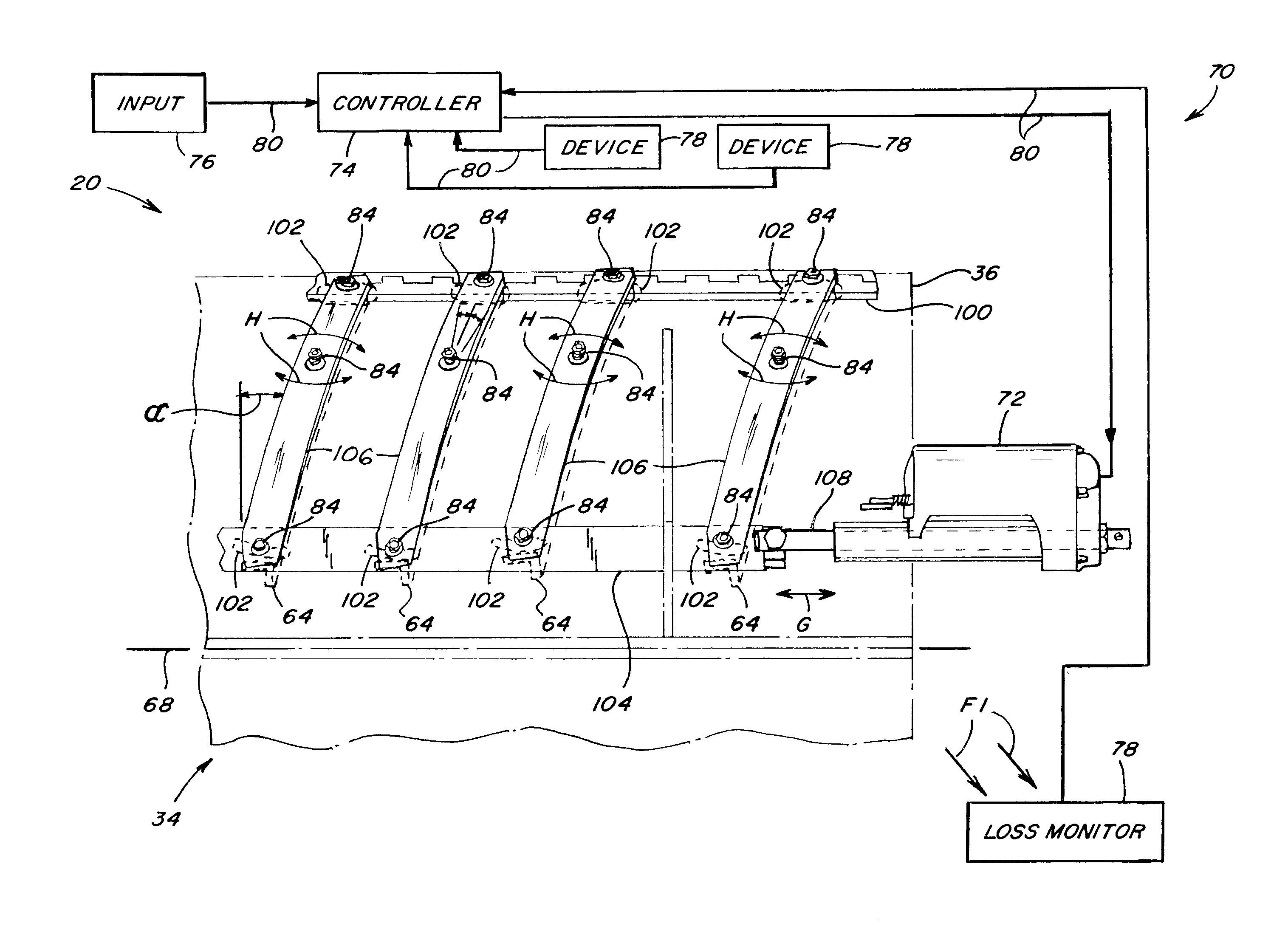
[0007]According to a preferred aspect of the invention the system and method enable adjustably controlling the position of the vane or vanes, including while the threshing system is operating, for improving threshing performance and other operating parameters. Such parameters can include, but are not limited to, throughput, power consumption, and grain loss, and in particular, grain not threshed or separated from crop residue and thus which is carried through the body of the combine and lost by discharge from the combine with the residue. The vane position preferably comprises, but is not limited to, an angular position, particularly the pitch angle, relative to a reference such as a line or plane perpendicular to the axis of rotation of the rotor.

Problems solved by technology

While manual setting of threshing cage vane position has utility, it suffers from shortcomings including inability to adjust during operation of the threshing system, particularly in real time, responsive to changing conditions, for instance, responsive to changing conditions such as varying crop conditions within a field, e.g., population / yield, moisture content; atmospheric conditions, e.g., humidity; ground speed; grain loss; and the like, and changes in other operating parameters or settings made in process, such as, but not limited to: threshing rotor speed; concave gap; power consumption, and the like.
Grain cracking and other damage can occur as a result of over aggressive threshing, which can result from high rotor speed and / or an undersized concave gap size.
Higher than desired grain loss can result from settings of other systems of the combine, e.g., the grain cleaning system, and also from the threshing cage vane setting.
In this latter regard, a steeper or more vertical vane pitch angle setting will typically result in the crop material flowing in a correspondingly steeper or tighter helical path through that region of the threshing cage, and thus greater dwell time in the threshing system for threshing and separating; while a less steep or more horizontal vane pitch angle will result in crop material flow at a less steep or looser helix and less dwell time, threshing and separating, which can result in increased grain loss.

Method used


Image

  • Remote control adjustable threshing cage vane system and method
  • Remote control adjustable threshing cage vane system and method
  • Remote control adjustable threshing cage vane system and method

Examples


Embodiment Construction

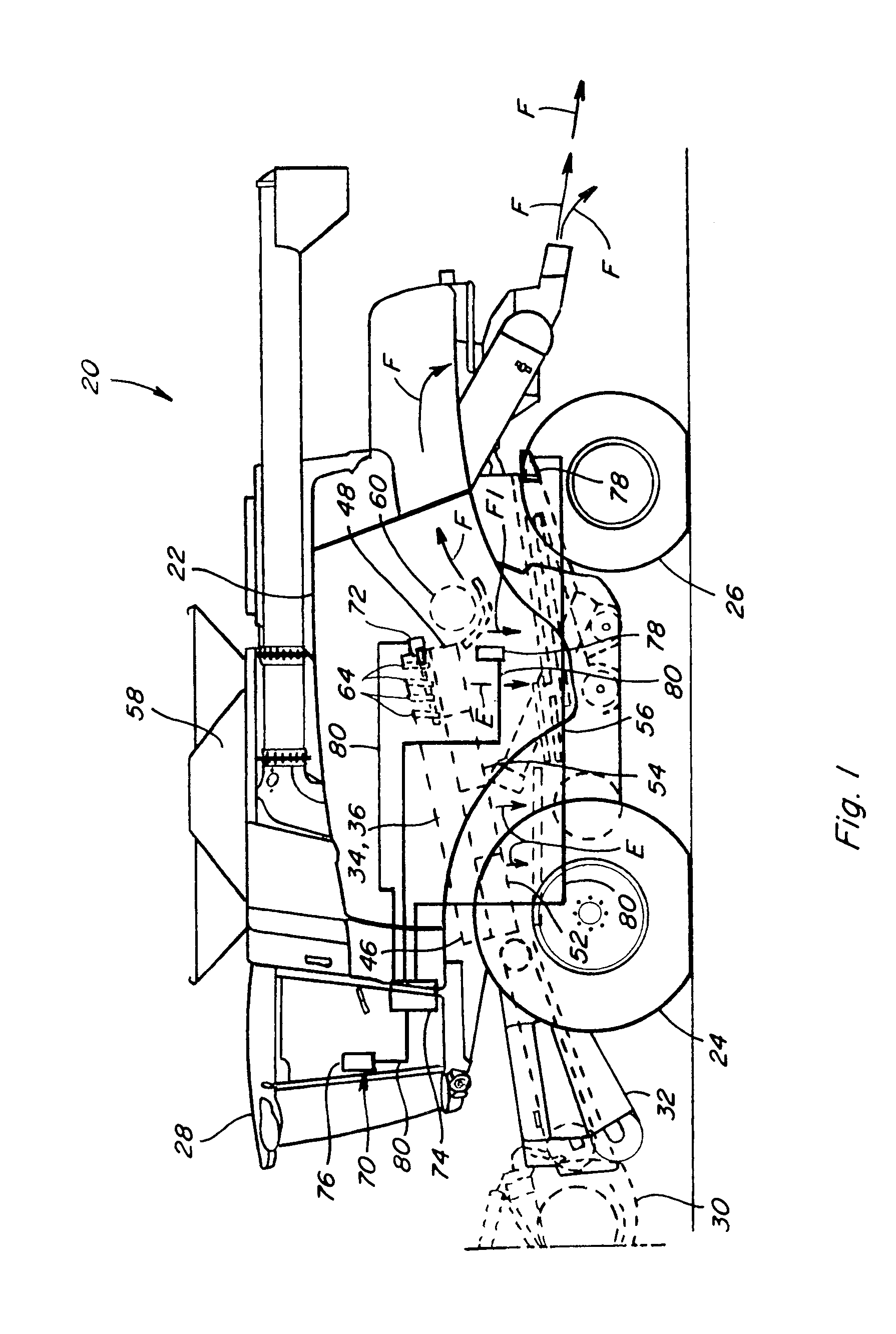
[0023]Referring now to the drawings wherein several preferred embodiments of the invention are shown, in FIG. 1 there is shown a representative self-propelled combine 20. Combine 20 includes a body 22 supported on front drive wheels 24 and rear steerable wheels 26. An operator cabin 28 sits atop a front or forward end of body 22, and from which an operator will control operation of the combine in the well known manner. Combine 20 is provided with a header 30 for cutting the standing crop and conveying the cut crop to a feeder 32, also in the well known manner. Feeder 32 forms the cut crop material into a generally flat mat and conveys the mat rearwardly into an inlet end of a threshing system 34, again, in the well known manner.

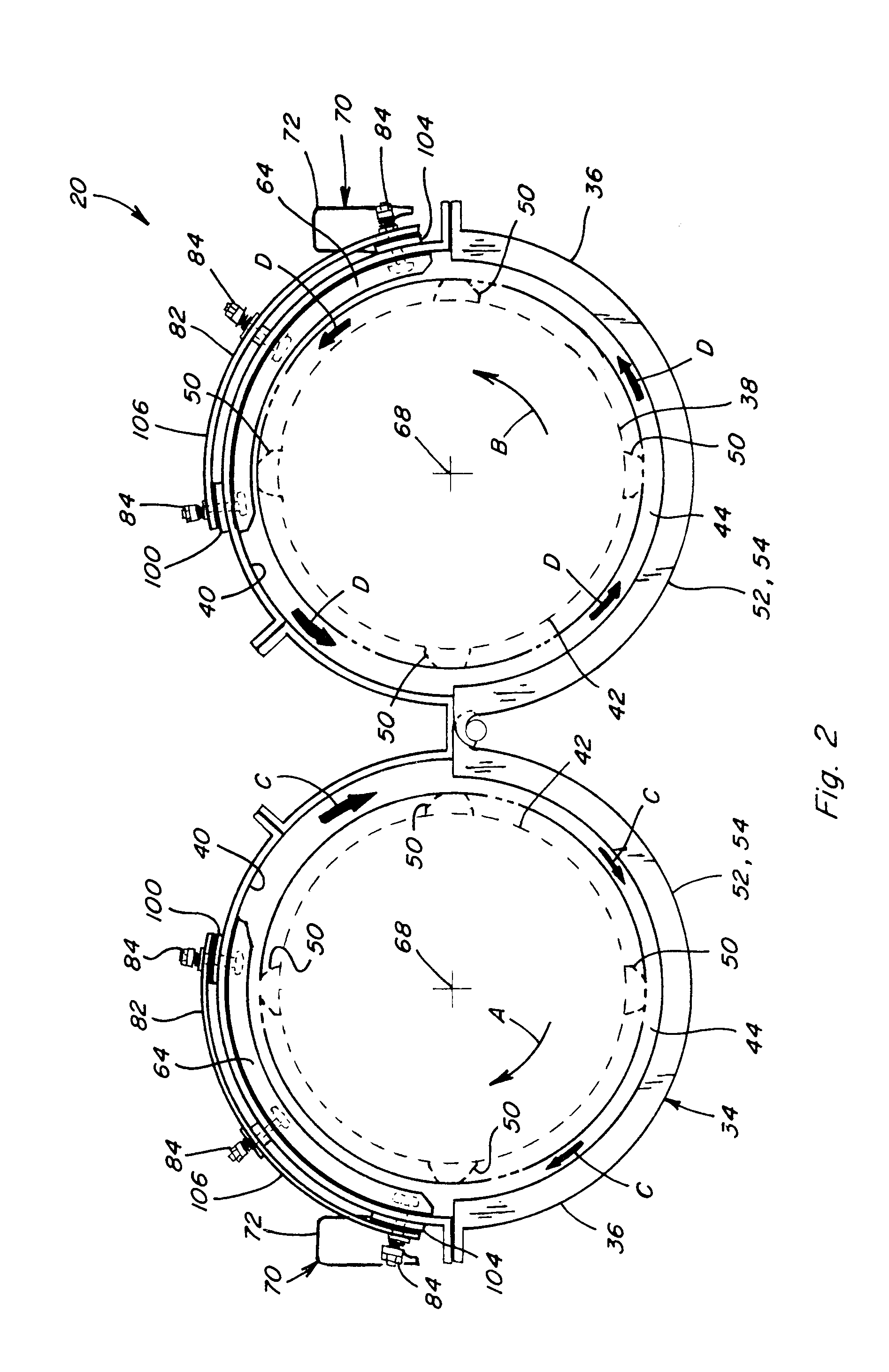
[0024]Referring also to FIG. 2, threshing system 34 here is depicted as a twin, axial rotor type system, including a pair of side by side, fore and aft extending, generally cylindrical threshing casing or cages 36, each extending about and containing a genera...


PUM


Abstract

A system and method for remote control of an adjustable threshing cage vane, including while the threshing system is operating, for improving threshing performance and other operating parameters, utilizes an actuator in connection with the at least one vane and remotely controllable for adjustably varying the position thereof, e.g, pitch angle, within the cage for altering the path of the flow of the crop material therethrough. The remote control can be via an automatic controller to provide control responsive to one or more monitored operating parameters, such as grain loss, grain flow, ground speed, and / or throughput, as well as inputted commands.

Description

TECHNICAL FIELD[0001]This invention relates generally to an adjustable threshing cage vane for the threshing system of an agricultural combine, and more particularly, to a system and method for remote control of an adjustable threshing cage vane, e.g., the pitch angle thereof, including while the threshing system is operating, for improving threshing performance and other operating parameters.BACKGROUND ART[0002]It is known to utilize a plurality of vanes on the inner surface of a threshing rotor cage or casing to assist in guiding or directing the movement of the crop material through the threshing system of a combine. It is further known that such vanes can be manually moved and secured in several positions or orientations, namely, pitch angles, for a variety of reasons, including for different crop types or conditions. In a basic form the vanes are be bolted on the cage or casing at several different pitch angles relative to the axis rotation of a rotor of the system. In a more c...

Claims


Application Information

Patent Timeline
IPC IPC(8): G06F7/00A01F12/28
CPCA01F7/067
Inventor FARLEY, HERBERT M.RICKETTS, JONATHAN E.MCKEE, JOHN M.FLICKINGER, WAYNE T.BALTZ, CLINTON T.PANIGRAHI, ASISH K.
Owner CNH IND AMERICA LLC
Learn More