Method of Electron Diffraction Tomography

a technology of electron diffraction and tomography, which is applied in the direction of material analysis using wave/particle radiation, instruments, nuclear engineering, etc., can solve the problems of x-ray diffraction being less suited to determining the structure of e.g. proteins, and the crystal size of crystals must be rather larg

Active Publication Date: 2012-01-05
FEI CO
View PDF3 Cites 12 Cited by
  • Summary
  • Abstract
  • Description
  • Claims
  • Application Information

AI Technical Summary

Problems solved by technology

A disadvantage of X-ray crystallography is that the size of the crystals must be rather large, e.g. 0.1 μm or more, because the interaction between the crystals and the X-ray beam is small.
For many inorganic crystals this is not a problem, as these can easily be grown to a size of 0.1 μm or more, but it proves to be extremely difficult to grow crystals of e.g. proteins to such a size.
X-ray diffraction is thus less suited for determining the structure of e.g. proteins.
Kolb proceeds to describe that working in TEM mode with a small beam of typically 50 nm diameter makes it nearly impossible to position the beam with any degree of accuracy on a crystal that is larger than the beam.
A disadvantage of said method is that not all TEM's are equipped with a scanning unit, as a result of which not all TEM's can operate in STEM mode.

Method used


Image

  • Method of Electron Diffraction Tomography
  • Method of Electron Diffraction Tomography
  • Method of Electron Diffraction Tomography

Examples


Embodiment Construction

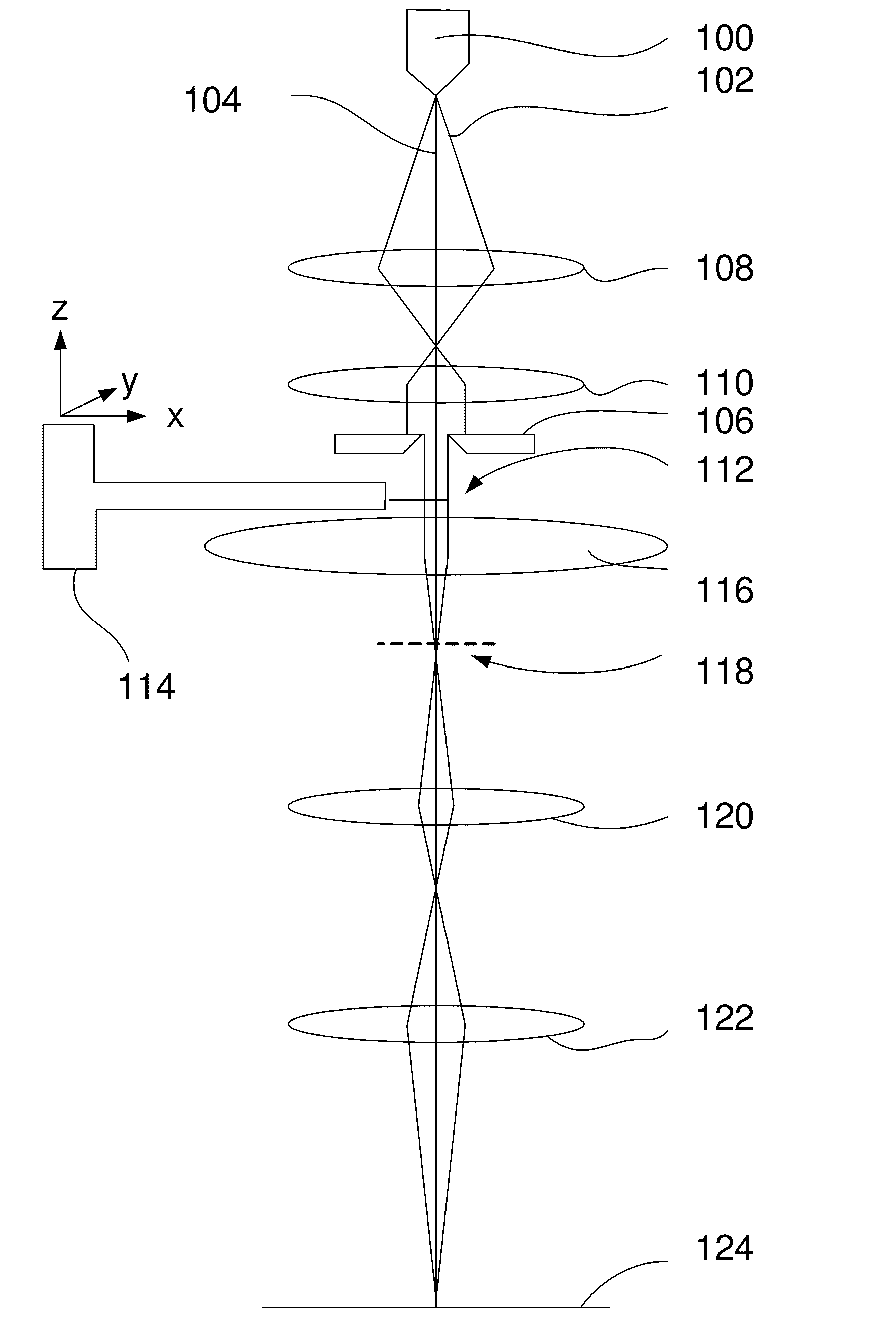
[0017]The method according to the invention is characterized in that the beam used for recording the diffraction patterns is a substantially parallel beam having a diameter larger than the size of the crystal.

[0018]By using a beam with a diameter larger than the crystal, and keeping this beam stationary with respect to the crystal while recording the diffraction pattern, the TEM used does not need to be equipped with a scanning unit for scanning the beam over the crystal.

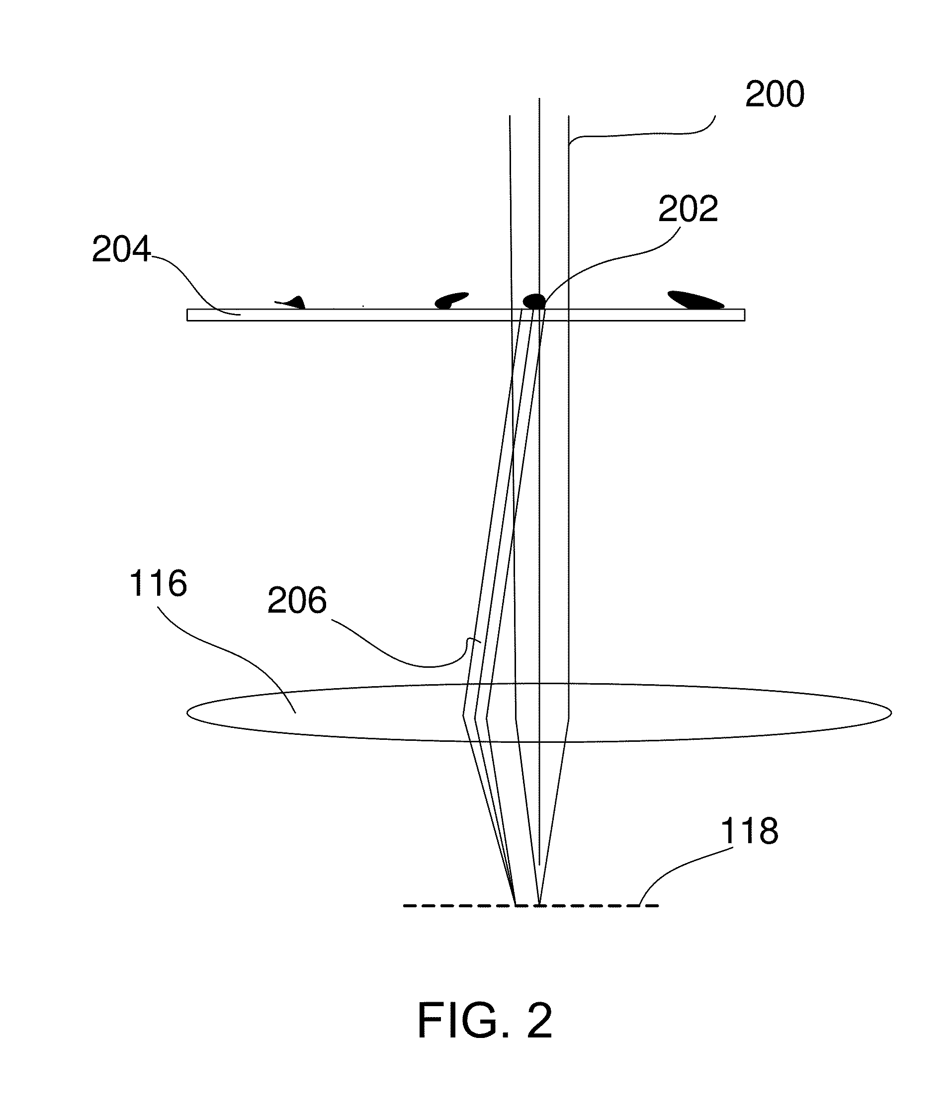
As the diameter of the beam is larger than the diameter of the crystal, the interaction volume, or scattering volume, also known as diffraction volume is the volume of the crystal itself, and thus for all tilt angles the same. This eases the normalization and post-processing otherwise needed when recording the diffraction patterns and / or analyzing the recorded diffraction patterns.

[0019]In an embodiment of the method according to the invention the centering of the crystal with respect to the beam involves shifting t...


PUM

PropertyMeasurementUnit
diameteraaaaaaaaaa
diameteraaaaaaaaaa
diameteraaaaaaaaaa

Abstract

The invention relates to a method for electron diffraction tomography in a Transmission Electron Microscope. Known methods involve using Scanning Transmission Electron Microscope, and use the scanned beam for STEM diffraction. The invention proposes to form the diffraction patterns with a stationary beam with a diameter slightly larger than the crystal, as a result of which a TEM without STEM unit can be used. Finding the crystal is done in TEM mode. Advantages of the method according to the invention are: a TEM without scanning unit can be used, and the diffraction volume is not depending on the orientation of the crystal, as the whole crystal is illuminated while obtaining the diffraction pattern.

Description

TECHNICAL FIELD OF THE INVENTION[0001]The invention relates to a method of determining the crystallographic structure of a crystal by electron diffraction tomography using an electron microscope.BACKGROUND OF THE INVENTION[0002]This method is known from “Towards automated diffraction tomography: Part I-Data acquisition”, U. Kolb et al., Ultramicroscopy 107 (2007) 507-513.[0003]There is great interest in determining the structure of macro-molecules, such as catalysts, proteins, viruses, DNA and RNA. The knowledge is of importance for understanding how e.g. proteins operate, how to produce, for example, more effective medicaments, enzymes, etc., and for example to understand why certain illnesses occur.[0004]A group of techniques known as crystallography is used to determine the structure of molecules, of which X-ray crystallography is the most well-known. Here a multitude of diffraction patterns is recorded by irradiating a crystal by a beam of X-rays, and a diffraction pattern of sa...

Claims


Application Information

Patent Timeline
Patent Type & Authority Applications(United States)
IPC IPC(8): G01N23/207
CPCG01N23/20058G01N2223/102G01N2223/309G01N2223/32G01N2223/3306G01N2223/418H01J2237/2611G01N2223/612H01J37/265H01J37/295H01J2237/20207H01J2237/26G01N2223/419
Inventor HE, HAIFENGVOIGT, ANDREAS
Owner FEI CO
Why Eureka
Try Eureka