Liquid crystal display device
- Summary
- Abstract
- Description
- Claims
- Application Information
AI Technical Summary
Benefits of technology
Problems solved by technology
Method used
Image
Examples
embodiment 1
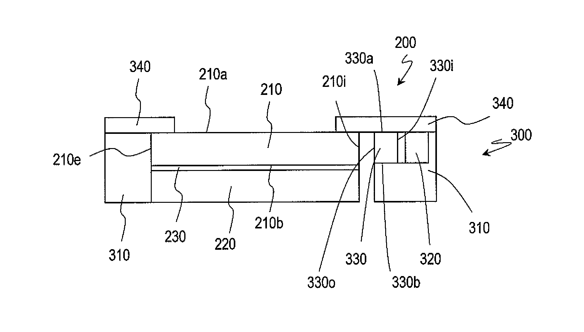
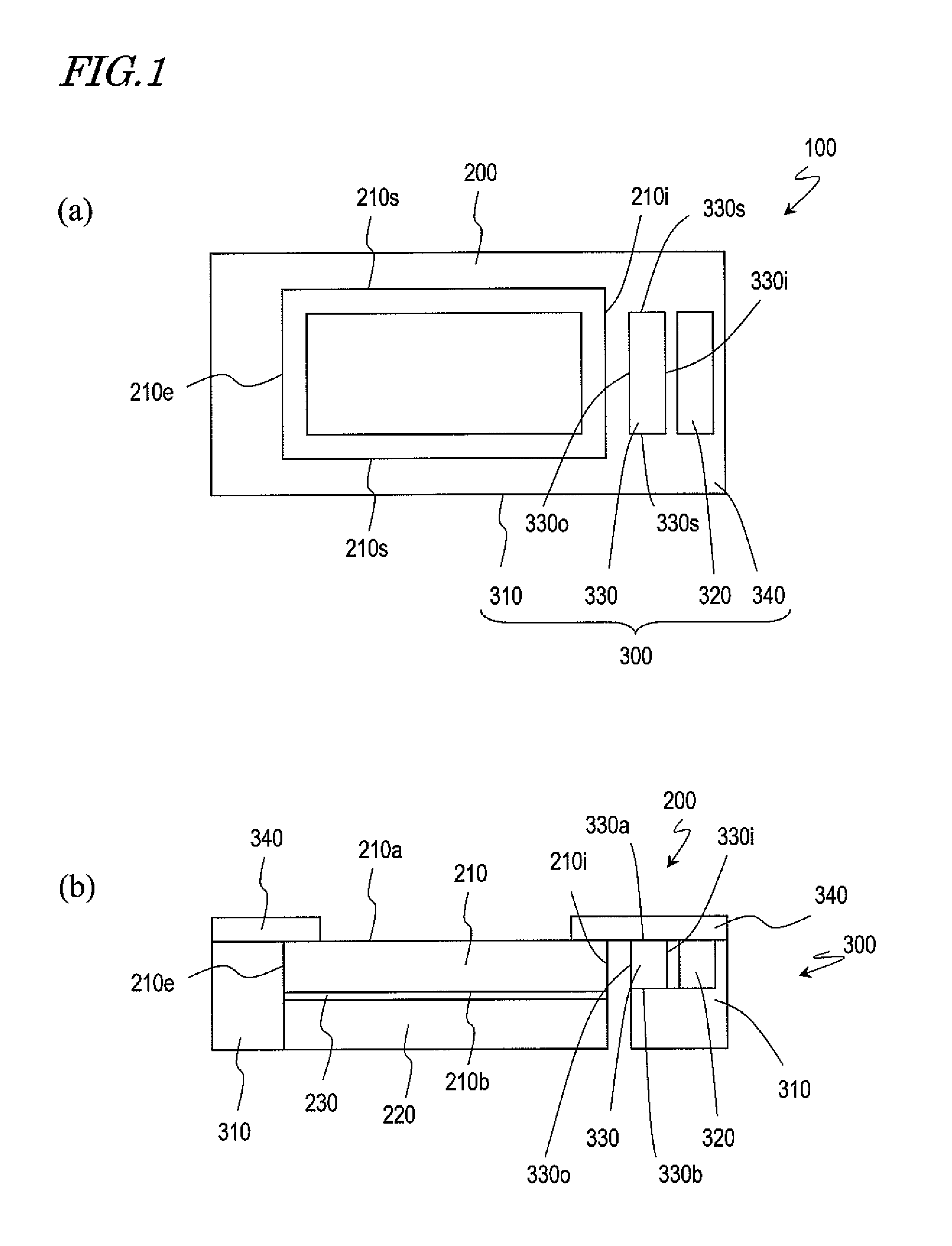
[0041]Hereinafter, a first embodiment of the liquid crystal display device according to the present invention will be described with reference to FIG. 1. FIG. 1(a) shows a schematic upper plan view of a liquid crystal display device 100 of the present embodiment, and FIG. 1(b) shows a schematic cross-sectional view of the liquid crystal display device 100.
[0042]The liquid crystal display device 100 includes a liquid crystal panel 200, and a sidelight unit 300 mounted to the liquid crystal panel 200. The liquid crystal panel 200 includes a front transparent substrate 210, a rear transparent substrate 220, and a liquid crystal layer 230 provided between the front transparent substrate 210 and the rear transparent substrate 220. Herein, the liquid crystal panel 200 is of the reflection mode. The front transparent substrate 210 and the rear transparent substrate 220 are made of glass, for example.
[0043]Although not shown, as necessary, electrodes, wiring lines, insulating layers and / or ...
embodiment 2
[0071]Hereinafter, with reference to FIG. 3, a second embodiment of the liquid crystal display device according to the present invention will be described. FIG. 3(a) shows a perspective view of a liquid crystal display device 100A of the present embodiment; FIG. 3(b) shows an exploded perspective view of the liquid crystal display device 100A; FIG. 3(c) shows an exploded perspective view of a sidelight unit 300A in the liquid crystal display device 100A; and FIG. 3(d) shows a schematic cross-sectional view of the liquid crystal display device 100A. For conciseness, any description similar to those of the liquid crystal display device 100 above will be omitted.
[0072]The liquid crystal display device 100A includes a liquid crystal panel 200 and the sidelight unit 300A. In the liquid crystal display device 100A, the sidelight unit 300A is mounted on the front face of the liquid crystal panel 200. In the liquid crystal display device 100A, too, light emitted from light sources 320 of th...
embodiment 3
[0090]In the above description, the sidelight unit is mounted to the front face of the liquid crystal panel; however, the present invention is not limited thereto. The sidelight unit may be mounted to the rear face of the liquid crystal panel.
[0091]Hereinafter, with reference to FIG. 4, a third embodiment of the liquid crystal display device according to the present invention will be described. FIG. 4(a) shows a perspective view of a liquid crystal display device 100B of the present embodiment; FIG. 4(b) shows an exploded perspective view of the liquid crystal display device 100B; FIG. 4(c) shows an exploded perspective view of a sidelight unit 300B in the liquid crystal display device 100B; and FIG. 4(d) shows a schematic cross-sectional view of the liquid crystal display device 100B. For conciseness, any description similar to those of the liquid crystal display devices 100 and 100A above will be omitted.
[0092]The liquid crystal display device 100B includes a liquid crystal panel ...
PUM
 Abstract
Description
Claims
Application Information
 - R&D
- Intellectual Property
- Life Sciences
- Materials
- Tech Scout
- Unparalleled Data Quality
- Higher Quality Content
- 60% Fewer Hallucinations
Browse by: Latest US Patents, China's latest patents, Technical Efficacy Thesaurus, Application Domain, Technology Topic, Popular Technical Reports.
© 2025 PatSnap. All rights reserved.Legal|Privacy policy|Modern Slavery Act Transparency Statement|Sitemap|About US| Contact US: help@patsnap.com


