High data rate connector system

a connector system and data rate technology, applied in the direction of coupling device connection, printed circuit aspect, coupling device details, etc., can solve the problems of high data rate, interface between the circuit board and the connector, and low data rate, so as to reduce the possibility of electrical separation

Inactive Publication Date: 2012-01-05
MOLEX INC
View PDF1 Cites 100 Cited by
  • Summary
  • Abstract
  • Description
  • Claims
  • Application Information

AI Technical Summary

Benefits of technology

[0007]A circuit board includes two pairs of signal vias and a ground via positioned between the two pairs. The signal vias are coupled to traces in a signal layer in the circuit board. The ground via is coupled a ground plane in the circuit board. Both the ground via and the signal vias are configured to receive tails of terminals from a connector configured to mount on the circuit board. One or more pinning vias may be positioned adjacent the ground via and are also coupled to the ground plane but don't receive tails from the connector. The combination of the ground and the one or more pinning vias work together to help provide electrical shielding and thus help prevent cross-talk between the two pairs of signal vias.
[0008]In an embodiment, a connector may be mounted to the circuit board so that pairs of signal

Problems solved by technology

For example, data rates of 10-15 Gbps are now being used and/or designed into systems and future systems can be expected to move toward 17-25 Gbps per data channel In addition, connectors are being made more compact, which makes it challenging to provide lower data-rates, let alone the higher data-rates that systems might be

Method used


Image

  • High data rate connector system
  • High data rate connector system
  • High data rate connector system

Examples


Embodiment Construction

[0025]The detailed description that follows describes exemplary embodiments and is not intended to be limited to the expressly disclosed combination(s). Therefore, unless otherwise noted, features disclosed herein may be combined together to form additional combinations that were not otherwise shown for purposes of brevity.

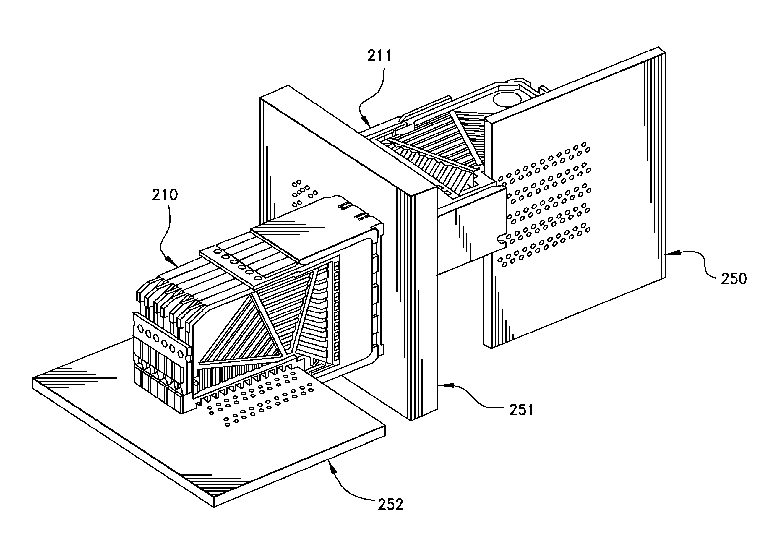
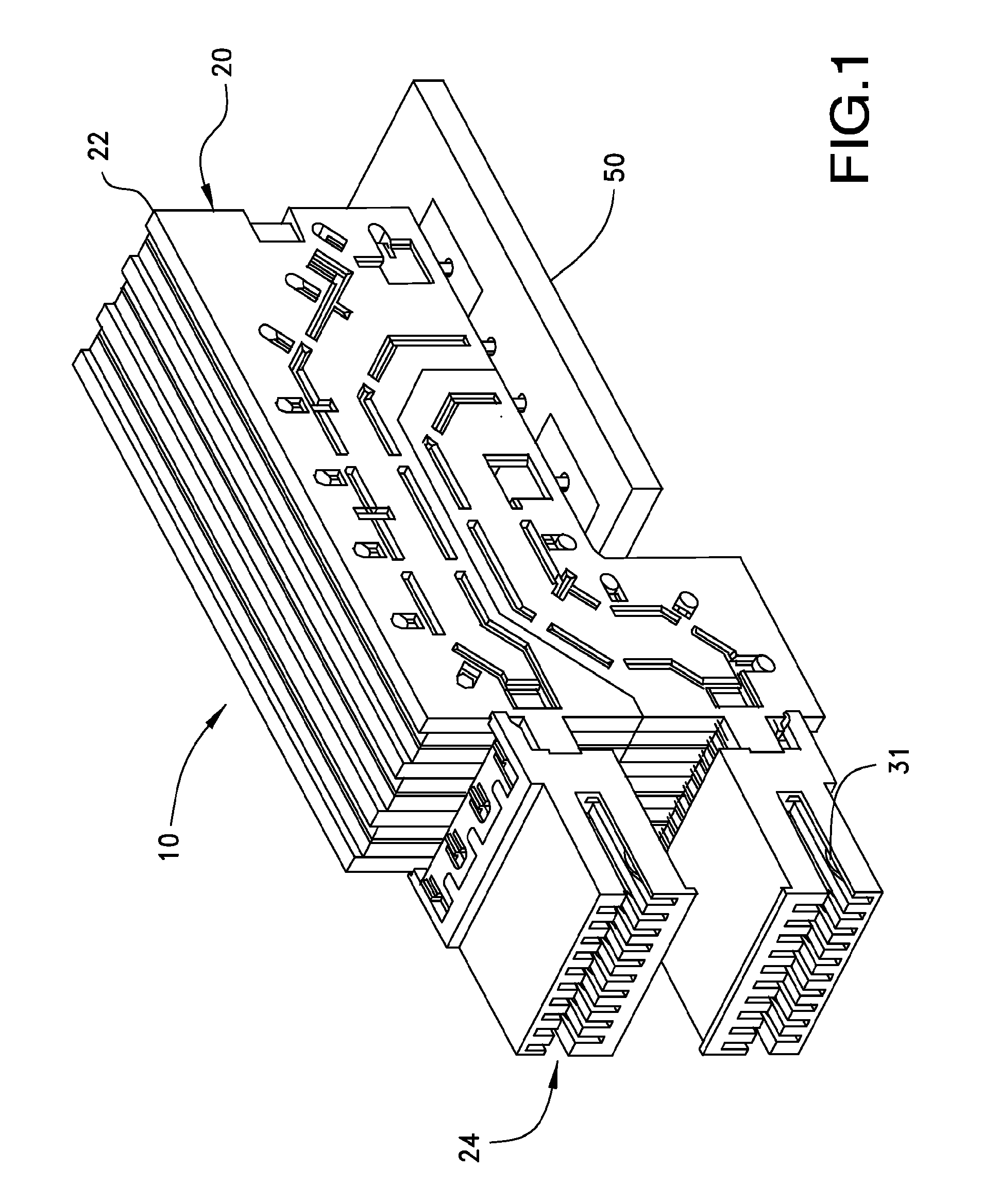
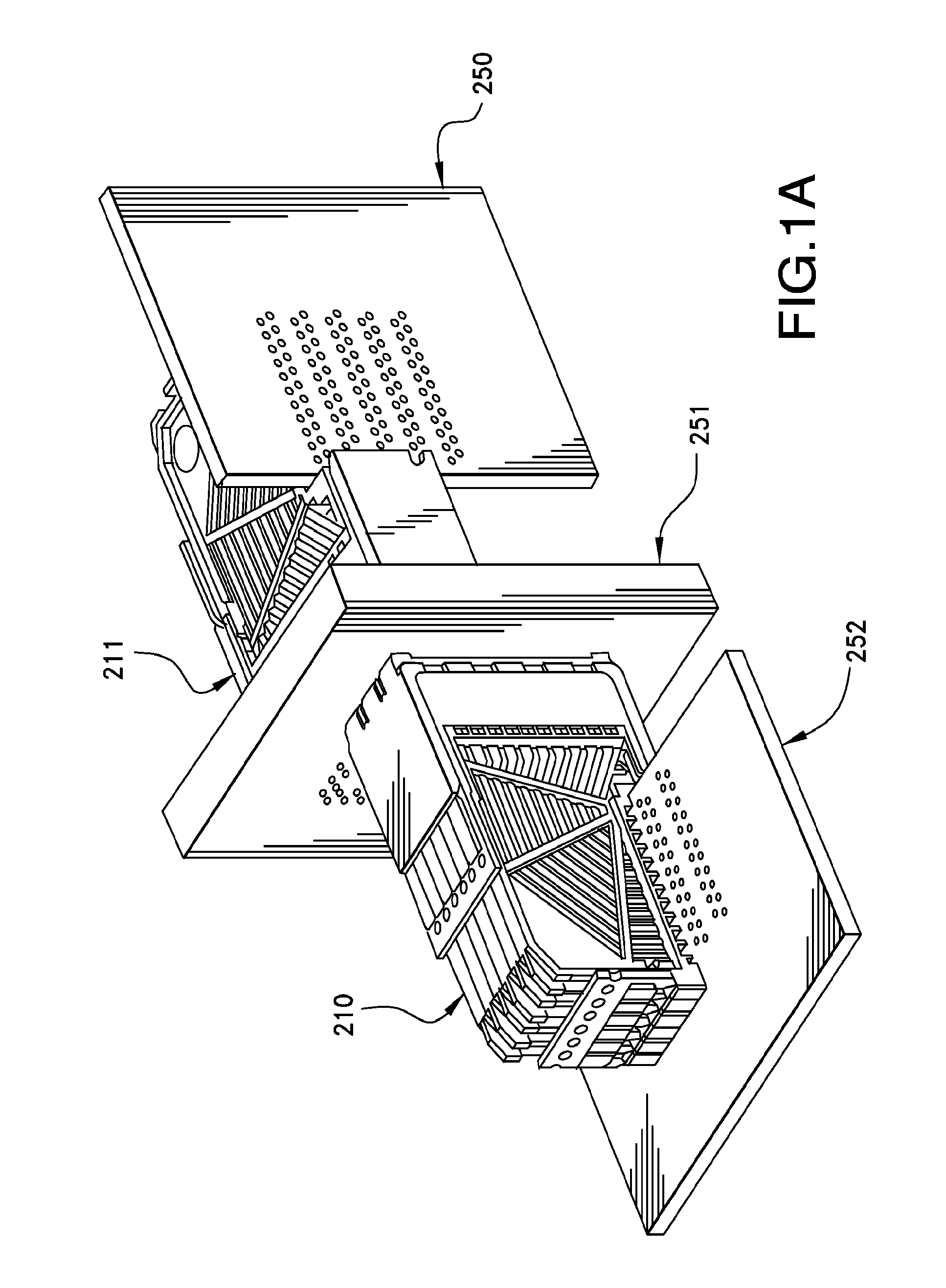
[0026]Systems that couple a connector to a circuit board, such as a printed circuit board, sometimes use what is known as a thru-hole configuration. Specifically, terminals in the connector include tails that are configured to be inserted into vias in a circuit board and then soldered in place. The vias thus couple the terminals in the connector to signal traces in the circuit board. Such a system provides good mechanical properties and allows a wide range of connectors to be supported by a circuit board. While there are a wide range of connector designs, the interface at the circuit board tends to be relatively similar. In general, certain vias are used to transm...


PUM


Abstract

A connector and circuit board assembly includes terminals in a connector that are mounted to vias in a circuit board. Signal and ground terminals are thus coupled to signal traces and ground planes in the circuit board. Additional pinning vias that are aligned with the ground vias may be provided in a circuit board to help improve electrical performance at the interface between the terminals in the connector and the signal traces in the circuit board. A signal collar may allow pairs of signal traces to be split and routed around two difference sides of a via before rejoining while maintaining close electrical proximity that provides for relatively consistent electrical coupling between the traces in the pair of signal traces.

Description

[0001]This application is a national phase of PCT Application No. PCT / US10 / 28487, filed Mar. 25, 2010, which in turn claims priority to U.S. Provisional Application No. 61 / 163,315, filed Mar. 25, 2009, both of which are incorporated herein by reference in their entirety.BACKGROUND OF THE INVENTION[0002]1. Field of the Invention[0003]The present invention relates to the field of connectors, more specifically to connectors suitable for high frequency signaling.[0004]2. Description of Related Art[0005]High-speed connectors are a widely used staple of high performance data-based systems. In general, the connectors connect different components together so that the components can communicate together at high data-rates. For example, data rates of 10-15 Gbps are now being used and / or designed into systems and future systems can be expected to move toward 17-25 Gbps per data channel In addition, connectors are being made more compact, which makes it challenging to provide lower data-rates, ...

Claims


Application Information

Patent Timeline
IPC IPC(8): H01R12/73H05K1/11
CPCH01R23/688H05K1/0222H05K2201/10189H05K2201/09609H05K2201/09618H05K1/0245H01R13/6587
Inventor CASHER, PATRICK R.REGNIER, KENT E.LANG, HAROLD KEITH
Owner MOLEX INC
Why Eureka
Try Eureka