Construction machine and control method thereof

a construction machine and control method technology, applied in the direction of process and machine control, vehicle position/course/altitude control, instruments, etc., can solve the problems of excessive electric charging, inability to start or drive a hybrid construction machine at very low, and electric motor/generator inhibition, etc., to achieve good driving capability, enhance engine braking force, and suppress a degree

Active Publication Date: 2012-01-05
NIHON KENKI CO LTD
View PDF15 Cites 86 Cited by
  • Summary
  • Abstract
  • Description
  • Claims
  • Application Information

AI Technical Summary

Benefits of technology

[0019]Preferably, the construction machine may further comprise an engine brake control unit for controlling a magnitude of an engine braking force; and the engine brake control unit may enhance the engine braking force when the construction machine starts and drives in a state where the forward driving gear position or the backward driving gear position of the transmission has been switched, and the electric motor / generator rotates reversely in the power running mode. This makes it possible to suppress a degree to which the engine revolves up. By controlling the magnitude of the engine braking force based on the accelerator opening, etc., the construction machine can implement a good driving capability in which the vehicle speed increases smoothly with high responsiveness to the driver's accelerator operation.
[0020]As the engine brake control unit, a hydraulic pump drivably coupled to the engine may be used. In general, the hydraulic pump is built into the construction machine as a hydraulic source for driving a loading system, a steering system and others. By controlling the output pressure (output flow rate as necessary) of the hydraulic pump, the magnitude of a rotation burden placed on the engine can be controlled.
[0021]When the vehicle speed increases and exceeds a predetermined value, after the forward driving gear position or the backward driving gear position of the transmission is switched to the direction opposite to the direction in which the construction machine is moving, and the electric motor / generator rotates reversely in the power running mode, and the construction machine starts, the forward driving gear position or the backward driving gear position may be returned to the direction in which the construction machine is moving, and the electric motor / generator may generate normal torque and maintain the power running mode. Thereafter, when the state of charge (SOC) in the electric storage device is deficient, the transmission gear position is upshifted, thereby causing the electric motor / generator to generate the electric power in the regenerative braking mode.

Problems solved by technology

However, for example, in a state where the electric storage device is fully charged, i.e., a large amount of electricity is stored in the electric storage device, excessive electric charging must be inhibited, and therefore the electric motor / generator must be inhibited from generating electric power.
In other words, during the state where the electric storage device is fully charged, the hybrid construction machine cannot start or drive at very low speed, and tends to be put in a failure-to-function state.
Therefore, the electric storage device is more likely to store a large amount of electricity, and the hybrid construction machine tends to be put in a failure-to-function state.

Method used


Image

  • Construction machine and control method thereof
  • Construction machine and control method thereof
  • Construction machine and control method thereof

Examples


Embodiment Construction

[0056]Hereinafter, a preferred embodiment of the present invention will be described with reference to the drawings.

[0057][Schematic Configuration of Drive System]

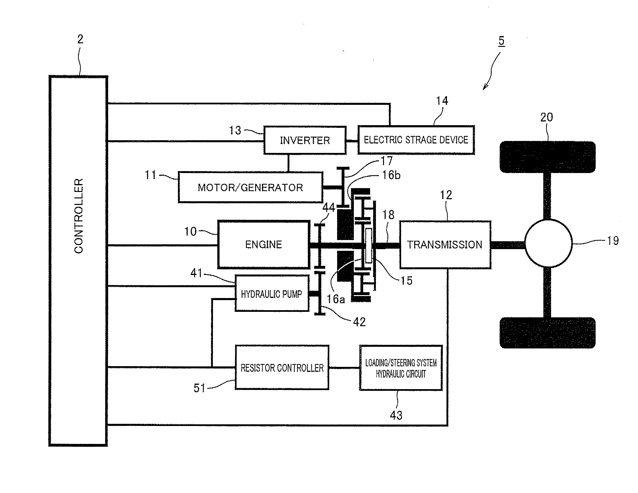
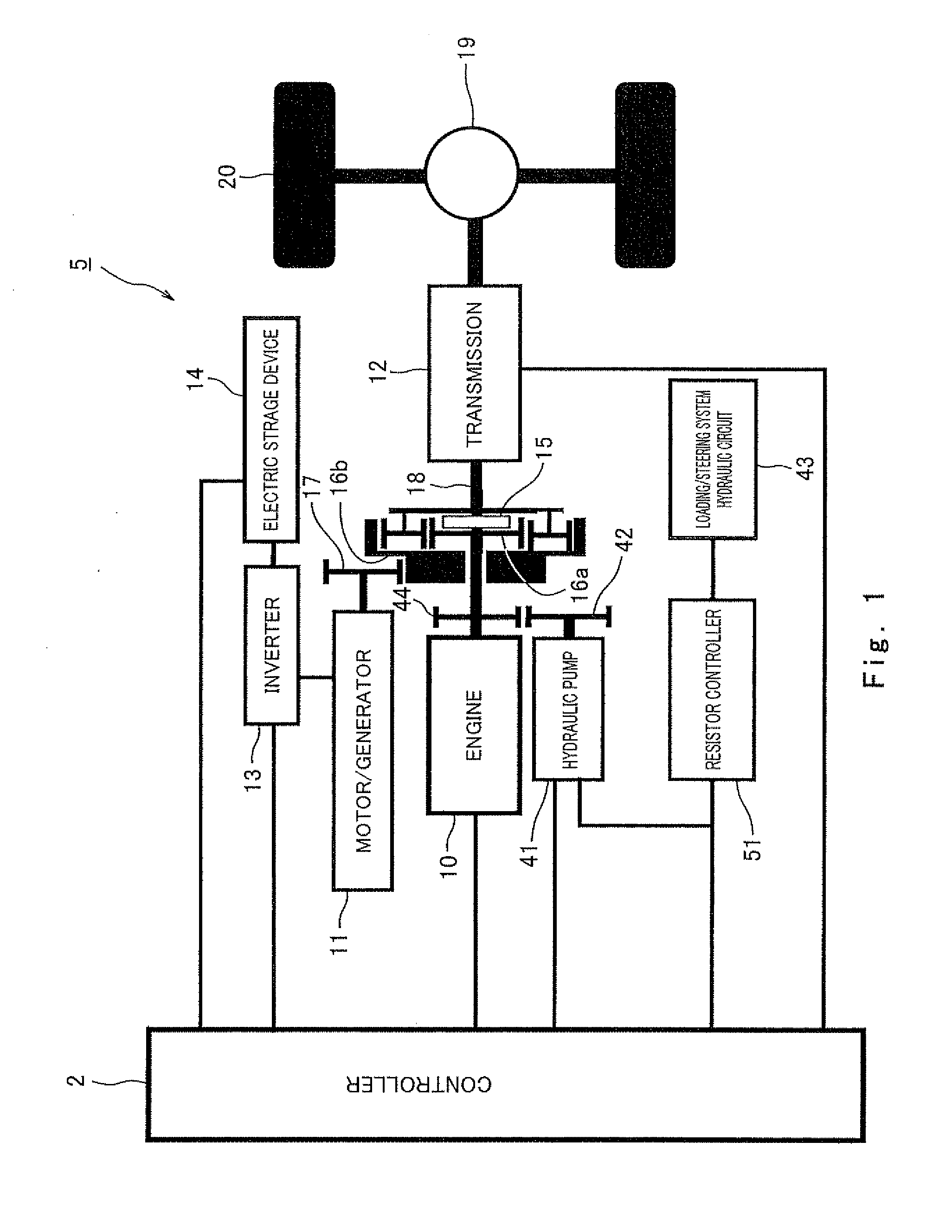
[0058]FIG. 1 is a block diagram showing a configuration of a drive system in a construction machine 1 according to an embodiment of the present invention. Turning now to FIG. 1, the construction machine 1 comprises an engine 10 and an electric motor / generator 11, as a driving power source. The construction machine 1 includes a hybrid drive system in which an epicyclic gearing composites a driving power of the engine 10 and a driving power of the electric motor / generator 11, and outputs the resulting composite driving power to drive wheels 20.

[0059]In the example of FIG. 1, the output shaft of the engine 10 is coupled to a sun gear 16a of the epicyclic gearing, while the output shaft of the electric motor / generator 11 is coupled to a gear 17 coupled to a ring gear 16b of the epicyclic gearing. A carrier 18 of the epicyclic ...


PUM


Abstract

A construction machine comprises an electric motor/generator; an engine; an epicyclic gearing for rotating the electric motor/generator reversely when speed of a rotation output to a drive wheel is zero during running of the engine; a transmission configured to switch between a forward driving gear position and a backward driving gear position; and a controller for controlling the engine, the electric motor/generator and the transmission, based on at least an accelerator opening, and a state of charge in an electric storage device; the controller being configured to switch the forward driving gear position or the backward driving gear position to a direction opposite to a direction in which the construction machine is moving, and cause the electric motor/generator to generate reverse torque in a power running mode, when the electric storage device is in a fully charged state and the accelerator has been pressed down by a driver.

Description

CROSS REFERENCE TO THE RELATED APPLICATION[0001]Japanese Patent Application No. 2007-93006 (U.S. patent application Ser. No. 12 / 580,161) and Japanese Patent Application No. 2010-119785, including specification, drawings and claims are incorporated herein by reference in its entirety.BACKGROUND OF THE INVENTION[0002]1. Field of the Invention[0003]The present invention generally relates to a hybrid construction machine including an engine and an electric motor / generator. More particularly, the present invention relates to a control technique suitable for wheel loaders and similar construction machines, which frequently generate great traction forces at very low speed.[0004]2. Description of the Related Art[0005]Japanese Laid-Open Patent Application Publication No. Hei. 9-14385 discloses a conventional hybrid vehicle including an internal combustion engine and an electric motor, as a driving power source, in which an output shaft of the engine is coupled to a sun gear of an epicyclic g...

Claims


Application Information

Patent Timeline
Patent Type & Authority Applications(United States)
IPC IPC(8): B60W10/08B60W10/18B60W10/10B60W10/06B60K6/48B60K6/547B60L50/16B60W10/30B60W20/00E02F9/20F16H59/18F16H59/74F16H61/02F16H61/21
CPCE02F9/2079B60W10/06B60W30/18127E02F9/2091E02F9/2075B60W2300/17B60W10/08B60W20/00B60W2540/10B60W2510/244B60W2520/06Y10T477/24Y02T10/6221B60K6/48Y02T10/6286B60W10/10Y02T10/62B60W30/18136B60W20/11
Inventor BAINO, MAKOTOBANDO, SOICHIROMATSUBA, HIDEKAZU
Owner NIHON KENKI CO LTD
Why Eureka
Try Eureka