[0014]The magnetically actuated reciprocating motor of the present invention solves the problems and provides the benefits identified above. That is to say, the present invention discloses a new and improved reciprocating motor comprising a fixed elongated magnetic
actuator having an axially charged permanent
magnet at each end of a shaft and a solenoid assembly having a solenoid made up of a wire coil that is wrapped around a nonferrous spool having an open center to provide an axially charged
magnetic field. The fixed shaft of the magnetic
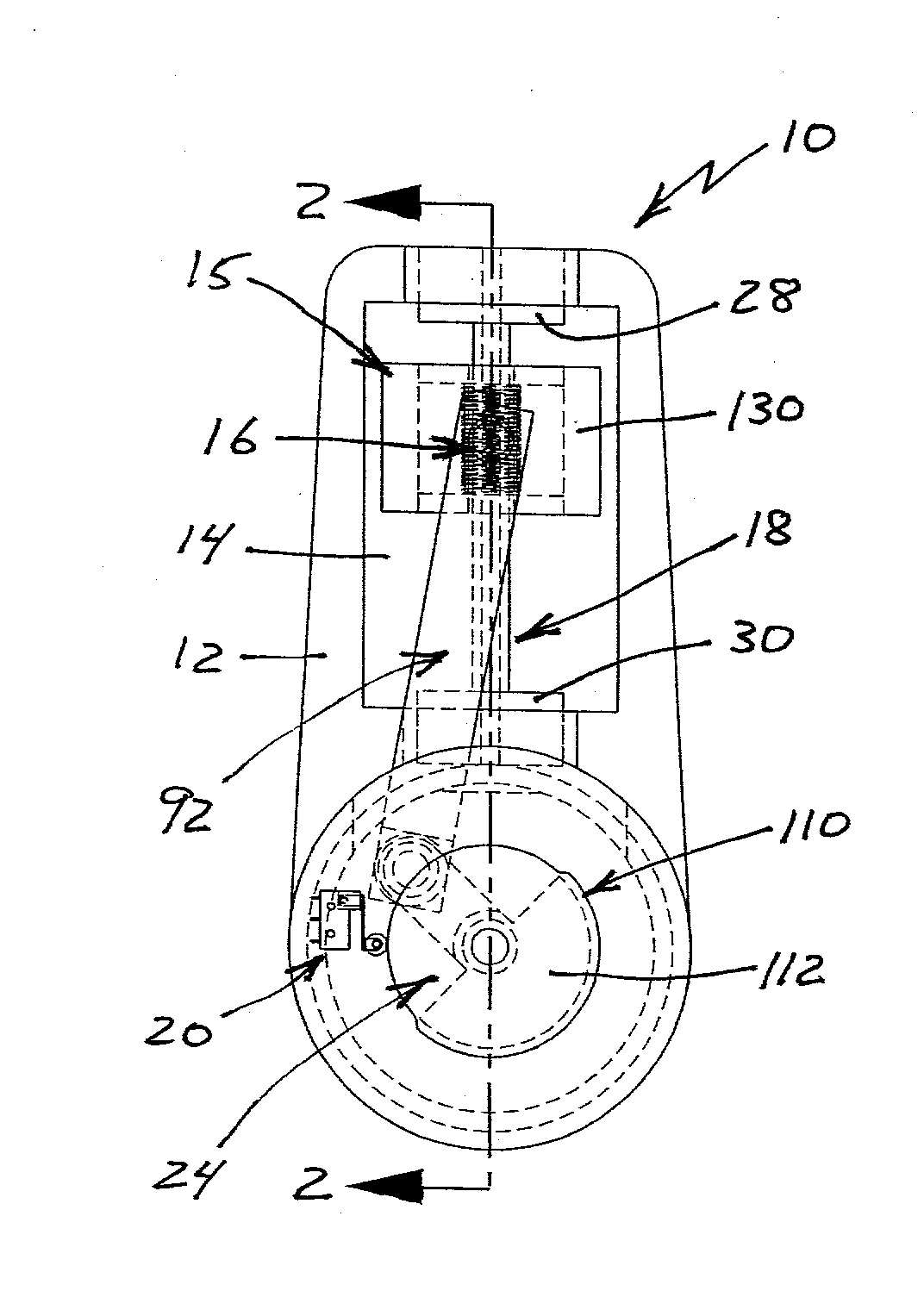
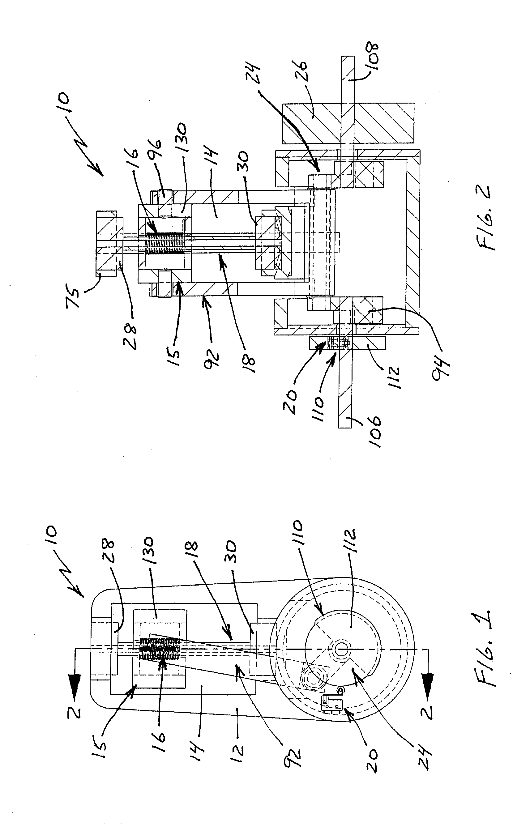
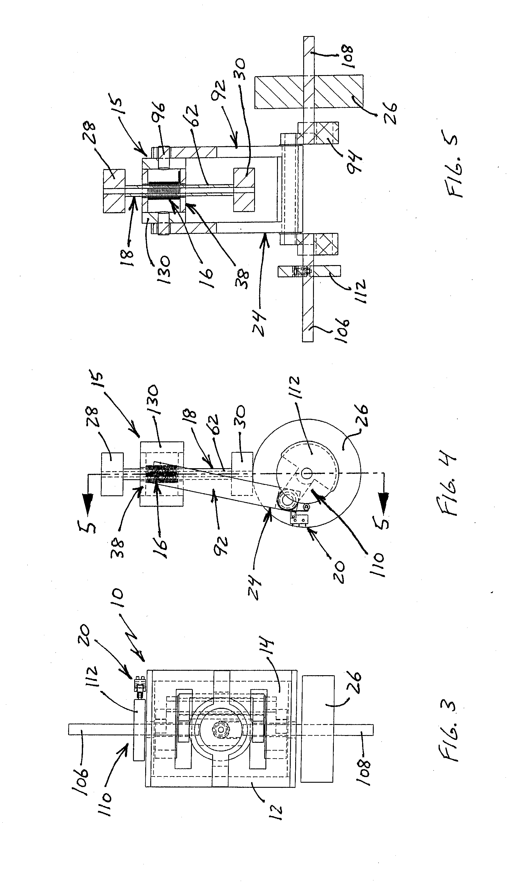
actuator is received in the open center of the spool in a manner that allows the solenoid assembly to reciprocate relative to the magnetic actuator. The magnetic polarities of the ends of the solenoid are rapidly switched such that one end of the solenoid, and therefore the solenoid assembly, is being attracted to the
magnet at one end of the shaft while the other end of the solenoid is being repelled by the magnet at the opposite end of the shaft. As a result, the solenoid alternates between being magnetically attracted to or repelled by each permanent magnet to reciprocate the solenoid assembly up and down the shaft and drive an output shaft that is operatively connected to the moving solenoid assembly. As with the '928 Application, the magnetically actuated reciprocating motor of the present invention does not utilize an
electromagnet. This arrangement eliminates the problems associated with the permanent magnets being attracted to the iron core of an
electromagnet, which can result in significant loss of efficiency and non-movement of the solenoid. The magnetically actuated reciprocating motor of the present invention does not rely on an
external source of power, such as a
prime mover or the like, to pivot, rotate or otherwise move the permanent magnets from an attracting position to a repelling position in order to reciprocally drive the magnetic actuator. The new reciprocating motor is relatively simple to operate, requires a limited number of moving components and is believed to be relatively inexpensive to manufacture. The magnetically actuated reciprocating motor of the present invention drives a
crankshaft so as to produce rotary power that is adaptable to a wide variety of reciprocating motor uses, including electrical power generation and vehicle motion.
[0017]In a preferred embodiment, the shaft has a tubular chamber, the first permanent magnet has a first extension member with an inward end extending into the tubular chamber from the first end of the shaft and the second permanent magnet has a second extension member with an inward end extending into the tubular chamber from the second end of the shaft. The inward end of the first extension member is disposed in spaced apart relation with the inward end of the second extension member to define a gap between the two extension members in the tubular chamber of the shaft. This configuration has been found to improve the performance of the motor of the present invention.
[0019]In contrast to the '928 Application, in which the solenoid is held stationary and the magnetic actuator reciprocates relative to the solenoid, in the present invention the solenoid (as part of the solenoid assembly) reciprocates around the shaft of the stationary magnetic actuator. In one embodiment, a magnet frame is utilized at each of the permanent magnets to interconnect the magnets with the frame and fix the magnetic actuator. The present embodiment has the
advantage of allowing heavier permanent magnets without the loss of energy that would be otherwise associated with reciprocating those magnets. As well known in the art, heavier weight magnets generally provide greater magnetic force, which can then be converted into increased
work output by the motor of the present invention.
[0020]Accordingly, the primary objective of the present invention is to provide a magnetically actuated reciprocating motor using reverse
magnetic switching that provides the advantages discussed above and overcomes the disadvantages and limitations associated with presently available magnetically powered reciprocating motors.
[0022]It is also an important object of the present invention to provide a magnetically actuated reciprocating motor that utilizes electromagnetic force to alternatively attract and repel a solenoid relative to a pair of oppositely positioned permanent magnets mounted at the ends of a shaft received through the solenoid that does not utilize an electromagnet so as to eliminate attraction between the permanent magnets and the iron core of the electromagnet.
[0024]It is also an object of the present invention to provide a magnetically actuated reciprocating motor that does not require utilization of a
prime mover or the like to provide the
magnetic switching necessary to magnetically reciprocate a solenoid and drive an output shaft connected thereto.

