
Piezoelectric generator unit using piezoelectric bimorph

Inactive Publication Date: 2012-01-12
PEOPLE&ENVIRONMENT
View PDF0 Cites 23 Cited by
  • Summary
  • Abstract
  • Description
  • Claims
  • Application Information

AI Technical Summary

Benefits of technology

[0011]Therefore, the present invention has been made in view of the above problems, and it is an object of the present invention to provide a piezoelectric generator unit using a piezoelectric bimorph which converts a linear motion into a rotary motion using simple pressure obtained due to walking or a moving load of a vehicle or load pressure obtained due to vibration so as to more effectively generate electrical energy.

Problems solved by technology

Further, since, if excessive impact is transmitted to the piezoelectric element, the piezoelectric element may be damaged, a structure to prevent excessive impact from being transmitted to the piezoelectric element while effectively transmitting external mechanical energy to the piezoelectric element is required.
Particularly, a piezoelectric element formed of ceramic has high brittleness and thus requires a housing to prevent damage to the piezoelectric element due to excessive external force while effectively transmitting mechanical energy to the piezoelectric element.
However, when continuous vibration and impact are transmitted to the piezoelectric element used in the piezoelectric generator, electrical connection between the piezoelectric element and the electrode is severed.
Therefore, a generator unit, which maintains electrical connection between the piezoelectric element and the electrode in spite of such vibration and impact, or a system of the generator unit needs to be developed, but does not obtain satisfactory results so far.

Method used


Image

  • Piezoelectric generator unit using piezoelectric bimorph
  • Piezoelectric generator unit using piezoelectric bimorph
  • Piezoelectric generator unit using piezoelectric bimorph

Examples


Embodiment Construction

[0028]Hereinafter, preferred embodiments of the present invention will be described in detail with reference to the annexed drawings so that those skilled in the art may easily embody the present invention. However, the present invention is not limited to the embodiments and the embodiments may be variously modified.

[0029]Specific terms used in the following description are given only to describe specific embodiments and are not intended to limit the present invention. Singular forms used in the following description include plural forms unless they apparently represent opposite meanings. The meaning of “including” used in the following description is intended to embody specific properties, regions, integers, steps, operations, elements and / or components, but is not intended to exclude presence or addition of other properties, regions, integers, steps, operations, elements, components and / or groups.

[0030]Although not defined differently, all terms including technical terms and scien...


PUM


Abstract

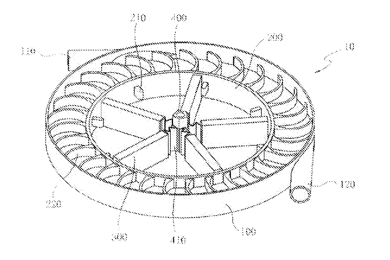
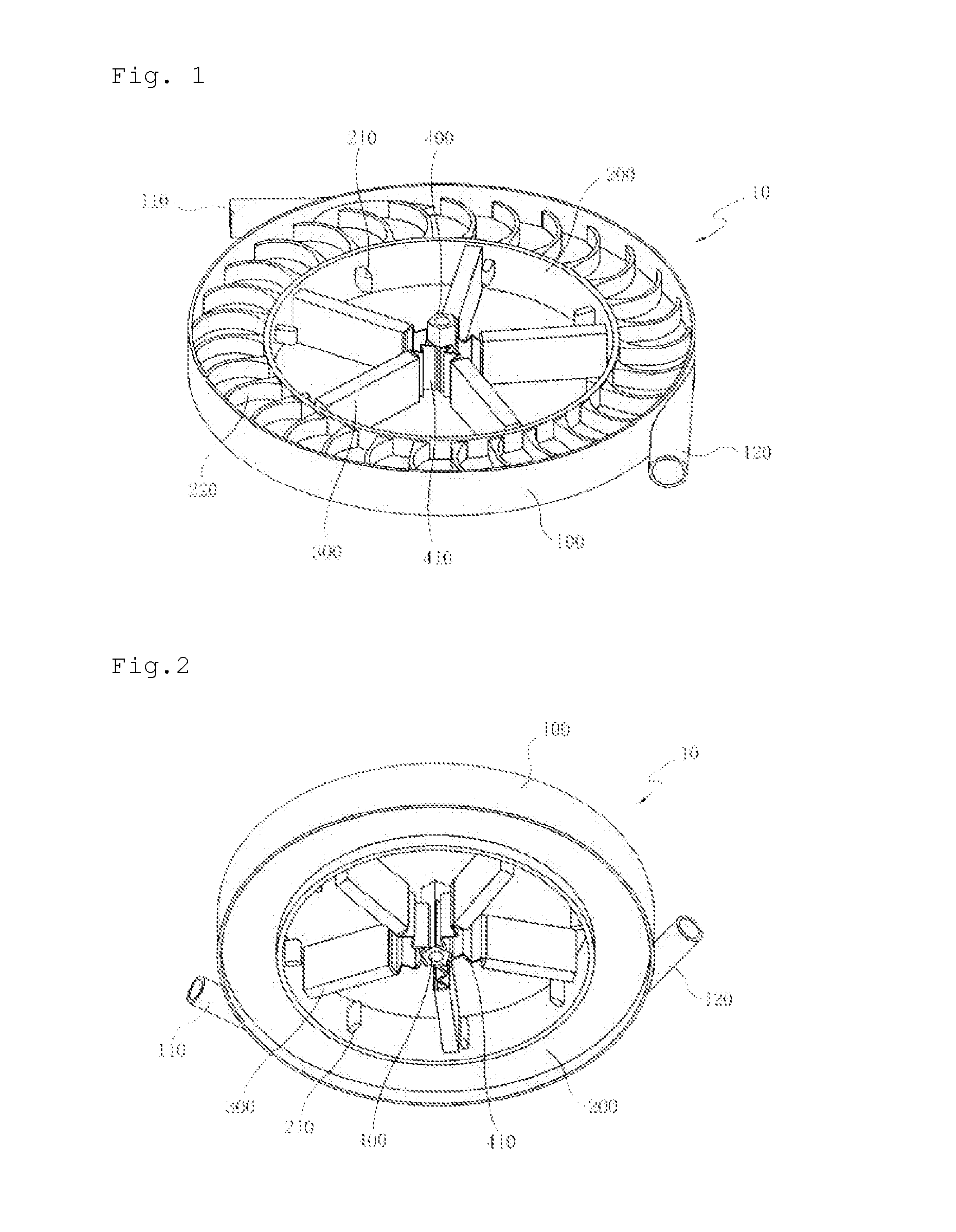
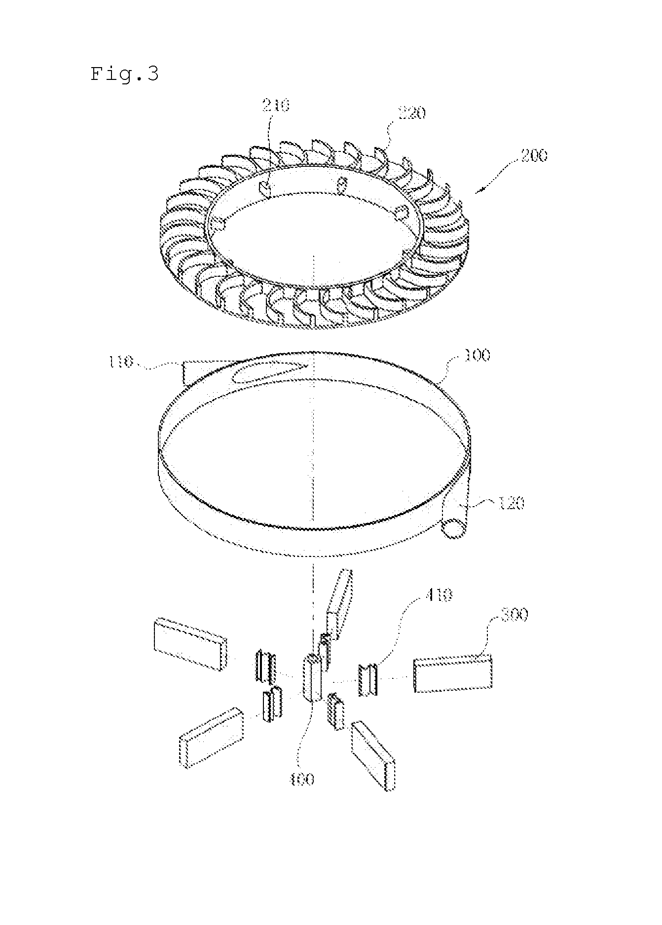
Disclosed herein is a piezoelectric generator unit using a piezoelectric bimorph. The piezoelectric generator unit includes a cylindrical housing, a fly wheel rotated within the housing by external power and provided with plural protrusions arranged at a regular interval in the circumferential direction, a fluid ejection device transmitting power to the fly wheel by ejecting a fluid or air onto impellers of the fly wheel to rotate the fly wheel, plural piezoelectric members installed radially and contacting the plural protrusions to generate electricity due to impact, and a central shaft connected to the plural piezoelectric members via connection members. The piezoelectric generator unit effectively converts a linear motion into a rotary motion simply using slight impact or vibration so as to effectively generate electrical energy, generates high output at low input so as to improve power generation efficiency, and is applicable to various fields using a moving load.

Description

BACKGROUND OF THE INVENTION[0001]1. Field of the Invention[0002]The present invention relates to a piezoelectric generator unit, and more particularly to a piezoelectric generator unit using a piezoelectric bimorph which converts a linear motion into a rotary motion using simple pressure obtained due to walking or a moving load of a vehicle or load pressure obtained due to vibration so as to more effectively generate electrical energy.[0003]2. Description of the Related Art[0004]In general, piezoelectric materials are used as converters to convert mechanical energy into electrical energy and are applied to various fields. A large number of materials including inorganic materials and organic materials are known as materials to exhibit piezoelectric characteristics.[0005]A piezoelectric element is a device which generates voltage by means of force applied thereto and changes an intensity of voltage generated according to intensity of the applied force.[0006]When a piezoelectric genera...

Claims


Application Information

Patent Timeline
IPC IPC(8): H02N2/18
CPCH02N2/18
Inventor OH, JEONG HWAN
Owner PEOPLE&ENVIRONMENT
Learn More