Method and apparatus for printing a periodic pattern with a large depth of focus

a technology of depth of focus and periodic pattern, applied in the field of photolithography, can solve the problems of narrow depth of field, increasing difficulty, and sensitive distance in the intensity distribution of self-images and sub-images

Active Publication Date: 2012-01-12
EULITHA
View PDF0 Cites 24 Cited by
  • Summary
  • Abstract
  • Description
  • Claims
  • Application Information

AI Technical Summary

Benefits of technology

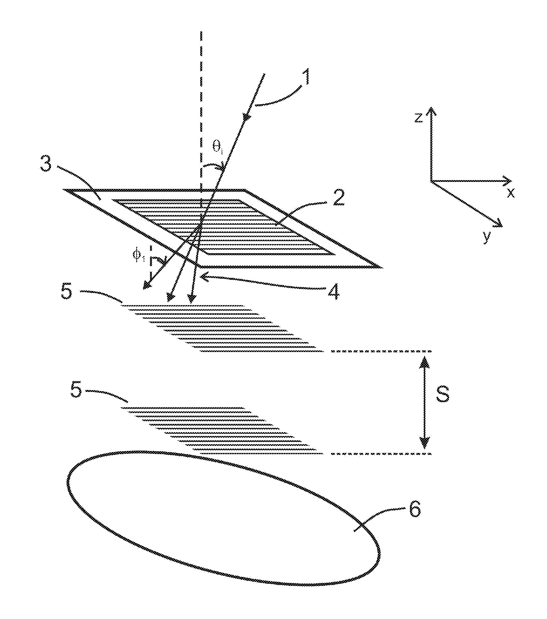
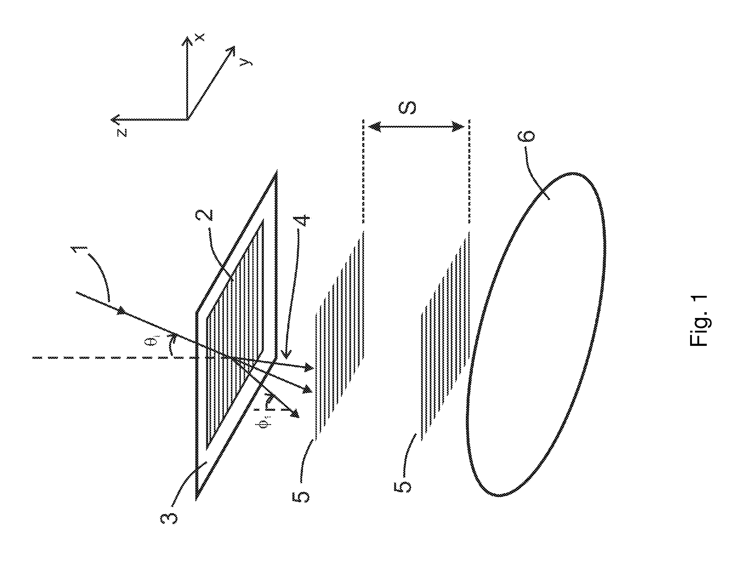
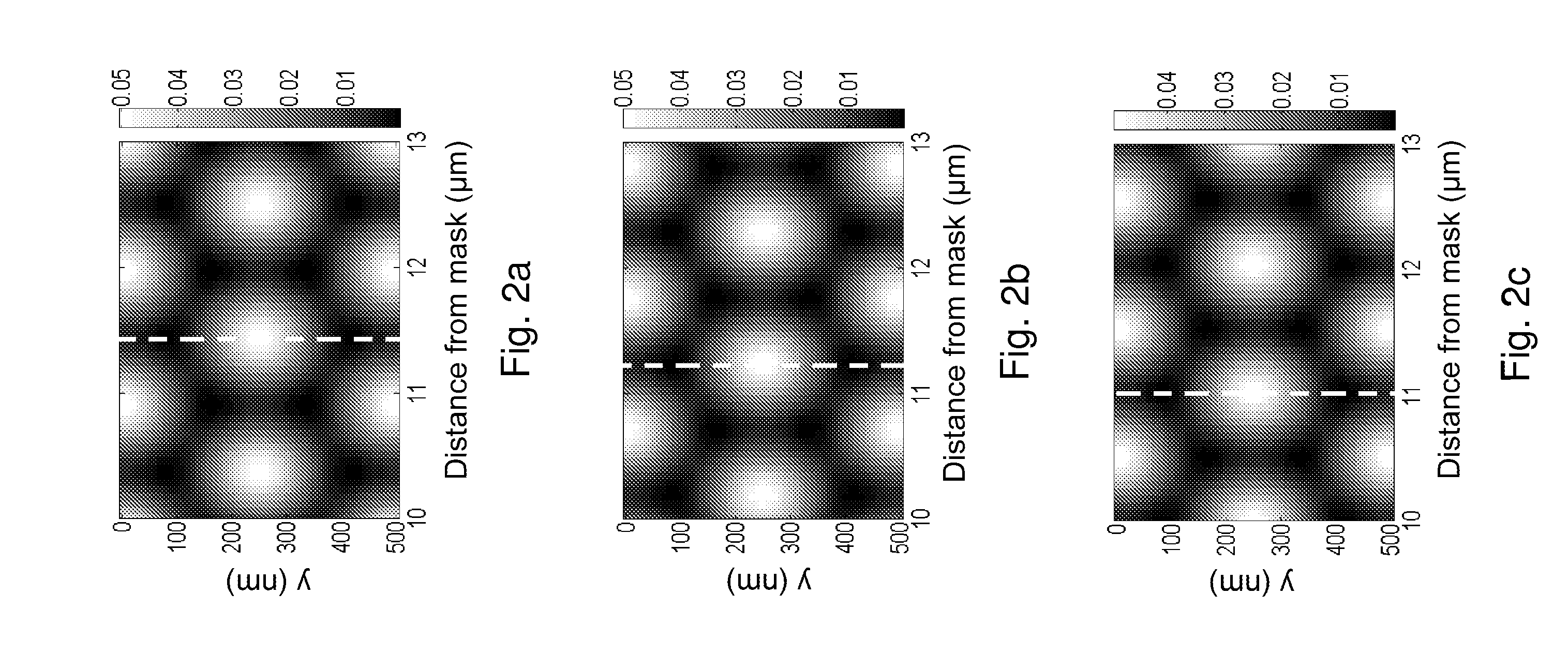
[0028]By selecting the angular range so that the substrate is exposed to substantially the average of the range of transversal intensity distributions that are formed between Talbot image planes by illuminating the mask pattern with a single angle of incidence, an equivalent exposure to that produced by the ATL or DTL techniques is achieved. For patterns that are periodic in one direction, the present invention therefore offers the same major advantage as the ATL and DTL techniques by enabling high-resolution patterns to be printed with a large depth of field. Since a laser may be employed as the illumination source it overcomes the main drawback of ATL, and since it does not require relative displacement of the substrate with respect to the mask during the exposure it overcomes the main drawback of DTL.

Problems solved by technology

With the Talbot technique, however, the intensity distributions of the self-images and sub-images are very sensitive to the distance from the mask, that is, they have a very narrow depth of field.
This becomes increasingly more difficult as the grating period is reduced because the depths of field of the self-images and sub-images are proportional to the square of the pattern period.
Furthermore, if the pattern needs to be printed onto a substrate that is not very flat or has topographical features on its surface, or into a thick layer of photoresist, it may be impossible to achieve the desired result.
A drawback of ATL arising from equ.
The angular divergence of the different diffracted orders propagating from the mask produces spatial offsets between the orders at the substrate surface and therefore imperfect image reconstruction at the pattern edges, which becomes worse with increasing separation.
Fresnel diffraction at the edges of the diffracted orders also degrades the edges of the printed pattern, which likewise gets worse with increasing separation.
For these reasons laser sources, which have relatively small spectral bandwidth, are in most cases unsuitable for ATL.
A difficulty with applying non-laser sources, such as arc lamps or LEDs, to ATL is obtaining the combination of high power in the exposure beam (for ensuring high throughput in a production process) and also good beam collimation (for ensuring high-contrast Talbot imaging).
Obtaining good collimation from these sources requires spatial filtering of the output beam which generally results in a large loss of power.
A drawback of the DTL technique is that the exposure equipment needs to provide a controlled displacement of the substrate with respect to the mask during the exposure, which can increase system complexity and cost, and can reduce reliability.
Because these refinements incorporate the principles of the ATL and DTL techniques for increasing the depth of focus of the printed patterns, they necessarily have the same drawbacks of those techniques.

Method used


Image

  • Method and apparatus for printing a periodic pattern with a large depth of focus
  • Method and apparatus for printing a periodic pattern with a large depth of focus
  • Method and apparatus for printing a periodic pattern with a large depth of focus

Examples


first embodiment

[0089]In the above-described first embodiment of the invention, the light in the beam 29 illuminates the grating 36 with a range of angles of incidence in a sequential manner wherein the light in the beam 29 has a substantially uniform angle of incidence and the angle of the beam 29 is changed during the exposure. It should be understood that the manner for illuminating the grating 36 with light over a range of angles of incidence that is exemplified by this embodiment may be equivalently achieved using many alternative combinations and configurations of light source, optical and mechanical components, so is in no way restricted to the particular selection of source, beam-collimating optics and beam-deflecting elements selected here. In one possible variant, the angular scan of the beam with respect to the mask is instead performed by tilting the mask and wafer sub-system, as a unit, with respect to a stationary beam.

[0090]With reference now to FIG. 12 which schematically shows a se...

second embodiment

[0093]In the above-described second embodiment of the invention, the light in the beam 60 illuminates each point of the grating 64 with a range of angles of incidence in a sequential manner wherein the grating 64 is illuminated by light whose angle of incidence varies across the beam 60 and the beam 60 is translationally scanned with respect to the grating 64. It should be understood that the manner for illuminating the grating 64 with light over a range of angles of incidence that is exemplified in this embodiment may be equivalently achieved using many alternative combinations and configurations of light source, optical and mechanical components, so is in no way restricted to the particular selection of source, beam-forming optics and scanning components selected here. For example, the scanning may alternatively be performed by displacing the mask and wafer sub-system, as a unit, with respect to the beam.

[0094]In another variant of this embodiment, a different set of beam-forming ...

third embodiment

[0098]In the above-described third embodiment of the invention, the light in the beam 88 illuminates the grating 92 with a range of angles of incidence in a simultaneous manner wherein the grating 92 is illuminated by light having a range of angles of incidence at each point of the beam 88. It should be understood that the manner for illuminating the grating 92 with light over a range of angles of incidence that is exemplified by this embodiment may be equivalently achieved using many alternative combinations and configurations of light source, optical and mechanical components, so is in no way restricted to the particular selection of source and components selected here.

[0099]In another embodiment of the invention that is not illustrated here, but may regarded as a combination of the second and third embodiments, a set of beam forming optics similar to those of the third embodiment are employed to generate a beam whose light at each point of the beam has a range of angles in the xz...


PUM

PropertyMeasurementUnit
mean angleaaaaaaaaaa
photosensitiveaaaaaaaaaa
wavelengthaaaaaaaaaa

Abstract

A method for printing a desired pattern into a photosensitive layer that includes providing a mask bearing a pattern of linear features that are parallel to a first direction, arranging the layer parallel to and separated from said mask, generating substantially monochromatic light, and illuminating the mask pattern with said light over a range of angles of incidence in a plane parallel to said first direction, at substantially a single angle in an orthogonal plane of incidence and so that the light of each angle of incidence transmitted by the mask forms a light-field component at the layer whereby the integration of said components prints the desired pattern, wherein the range of angles is selected so that the integration of said components is substantially equivalent to an average of the range of transversal intensity distributions formed between Talbot image planes by light at one of the angles of incidence.

Description

CROSS-REFERENCE TO RELATED APPLICATIONS[0001]Not ApplicableSTATEMENT REGARDING FEDERALLY SPONSORED RESEARCH OR DEVELOPMENT[0002]Not ApplicableTHE NAMES OF THE PARTIES TO A JOINT RESEARCH AGREEMENT[0003]Not ApplicableINCORPORATION BY REFERENCE OF MATERIAL SUBMITTED ON A COMPACT DISC[0004]Not ApplicableBACKGROUND TO THE INVENTION[0005]1. Field of the Invention[0006]This invention generally relates to the field of photolithography as employed for the fabrication of micro- and nano-structures, and it relates particularly to the field of Talbot imaging as employed for transferring periodic patterns of features defined in a mask onto a photosensitive layer on a substrate, and more particularly to the printing of patterns that are periodic in one dimension.[0007]2. Description of Related Art[0008]Lithographic fabrication enables the formation of micro- and nano-patterns on surfaces. Photolithographic techniques achieve this by exposing a photosensitive surface to a light-field with an inte...

Claims


Application Information

Patent Timeline
Patent Type & Authority Applications(United States)
IPC IPC(8): G03F7/20G03B27/54
CPCG03B27/54G03F7/70408G03F7/7035G03F7/70325G03F7/265H01L21/0274
Inventor CLUBE, FRANCIS S. M.DAIS, CHRISTIANSOLAK, HARUN H.
Owner EULITHA
Why Eureka
Try Eureka